Page updated on: January 25, 2008
July 24, 2009
Epoxy Hot Box
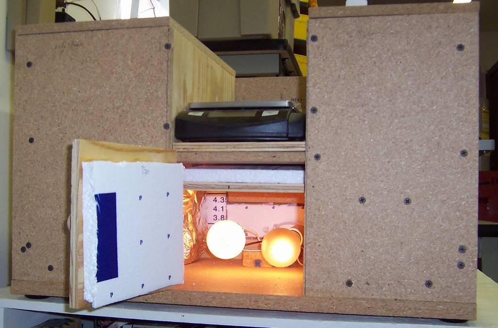
The purpose of the hot box is to keep the epoxy resin and hardener at about 105 degrees. At this temperature, it mixes well and is easily absorbed by the fiberglass. This makes building the plane quicker and easier.
I feel the hot box may be an ongoing project. As I progress further along, I may find a desire to change it. However, this is where I plan to start.
Update on using MGS' fast and slow hardener
When I first started out, I thought "WoW! This is great. MGS has both fast and slow hardener which can be mixed together to obtain any setup time desired. Well, that thought has been replaced.
The way I actually use these two types of hardner is to NOT mix them. I either use 100% slow or 100% fast. It was too much trouble to mix them together to get a set up time somewhere between the fast and slow. Also, I always seemed to guess wrong and the epoxy would start setting up quicker than I would like.
I have actually gone a step further in my thinking. As soon as I run out of fast hardener, I will only purchase slow hardener. I have found I do not have a need for a fast setup time. My normal procedure is to do a fiberglass layup one day, or evening. Then the next day or later, I use the layup. I have found 24-hours gives the slow epoxy enough time to cure.
Current feelings on the Epoxy Hot Box (2009)
I have been using the hot box for about 2-years and it is working great. I still think I would have made the box with doors on the front to access the resin and the epoxy, though now I would only have the slow hardner and not the fast.
The temperature in the hot box is set at 90 degrees F. Originally, I had wanted it to be 105 degrees F, but this was too hot. I found the epoxy thickend too quickly. Keeping the box at 90 degrees F seems to be just right.
The lightbulbs in the box glow dimmer or brighter depending on the ambient temperature in the factory. This is a change from before when the lights would flicker on and off. I'm not sure what changed, maybe it was setting the temperature to a lower value.
The interference on TV channel 2 has disappeared. This is due to the switch from analog to digital TV in the USA. The channel 2 signal is now being broadcast in the UHF frequency band, whereas before it was in the VHF band. Most of the VHF band is going to be used by other services.
A visitor to my website, Lloyd, was able to identify the TRIAC used in the dimmer. The X25783 is very similar to the Q2010LT. He found the cross reference here. The data sheet can be found here.
Current feelings on the Epoxy Hot Box (2007)
I have been using the epoxy hot box shown below for a few months. If I had it to do again, there are a few changes I would make. The individual push pumps I purchased did not work very well. The ones for the hardener clogged up after a couple of uses and I had no desire to be continually cleaning them. Also, the portion of the resin and hardner in the part of the pumps that are outside of the hot box cooled, thus defeating the purpose of the hot box! So I abandoned the idea of pumping out the epoxy.
I am now pouring the epoxy directly from the containers into cups. Then using the cups to pour the epoxy onto the digital scale. This is working much better than the pumps. However, it is a bit awkward with the current design of the hot box. I must remove the top, pull out the containers of epoxy. Measure the amount I need, then replace the containers back in the hot box. Since I am using the top of the hot box as a surface for the containers and the cups, it takes a bit of juggling to remove and replace the containers inside.
If I had it to do over again, I would make the box with multiple front opening doors. One each for the resin, the fast hardener and the slow hardener. Then I would take the containers out and put them on top of the box. Pour the amount I needed and replace the containers back in the box. I think this would work much better and be faster.
The thermostat is not working as well I was hoping. It is working, but the lights used to heat the box are blinking on and off at a very fast rate. I was hoping the thermostat would find a light level which would maintain the temperature in the box and the light would remain at constant level, getting brighter or dimmer, gradually as the outside temperature changed and more or less heat would be needed to the maintain the proper temperature in the box. I think the problem has to do with hysterisis. There is not enough of it. I tried to fix the problem by burying the thermister in a piece of foam, hoping it would slow down the speed at which the thermister would detect a temperature change. This helped, but has not completely solved the problem. I may need to glue it to chunk of metal to slow down the change even more.
The thermostat was also causing some interference with channel two on the TV. I found I could turn the box the thermostat is mounted in and the interference would get worse and then go completely away, depending on which side was pointed toward my outdoor TV antenna. If I subscribed to cable TV, it probably would not be a problem. To fix this, I need to put the RF choke closer to the TRIAC or put in more high frequency decoupling capacitors near the TRIAC or I could mount the whole unit in a metal box. However, since I can eliminate the interference by turning the box, that is what I do. It is not a perfect solution, but it works and is quick!
Basic Design
The basic design came from Bernard Sius Cozy Page. I liked his third design ("Enter Hot Box #3"). So this is the box I decided to build.

|
|
| Epoxy Hot Box - front view | Epoxy Hot Box - opened |
Designing a Thermostat for the Epoxy Hot Box
Purpose:
This project was designed to be a thermostat to control an epoxy hot box. The epoxy needs to be kept at about 105 degrees F so it will be viscous enough to be easily mixed and absorbed by the fiberglass cloth.
A search for a suitable off-the-shelf thermostat did not yield any within a reasonable price range. This one was designed to meet that need. The components used are readily available (in 2006) and the cost for them is under $10.
The most recent version of the thermostat is shown first. As you scroll down, you will find descriptions of the other versions which were abandoned for one reason or another.
Third version of the thermostat design
Circuit:
|
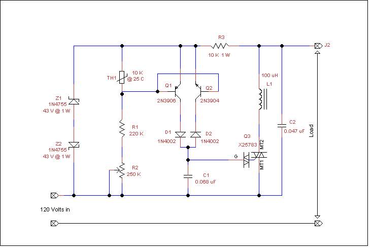
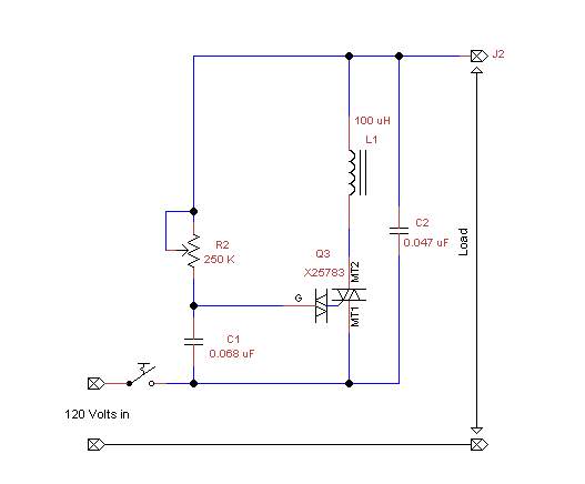
| Epoxy Box Thermostat |
In the third version, I decided to use the components of the dimmer switch I purchased (see second version below). The dimmer already had a TRIAC/DIAC (Q3) and it had the line filter (L1 & C2) to reduce radio frequency interference (RFI) when the TRIAC turned on. All I needed to add was a circuit to control the temperature. While searching the Internet for the pin out of the TRIAC in the dimmer circuit, I happened across Manfred Mornhinwegsweb page titled "Thermostat for room heater". WoW! This was EXACTLY the circuit I was looking for.
Manfreds Circuit:
|
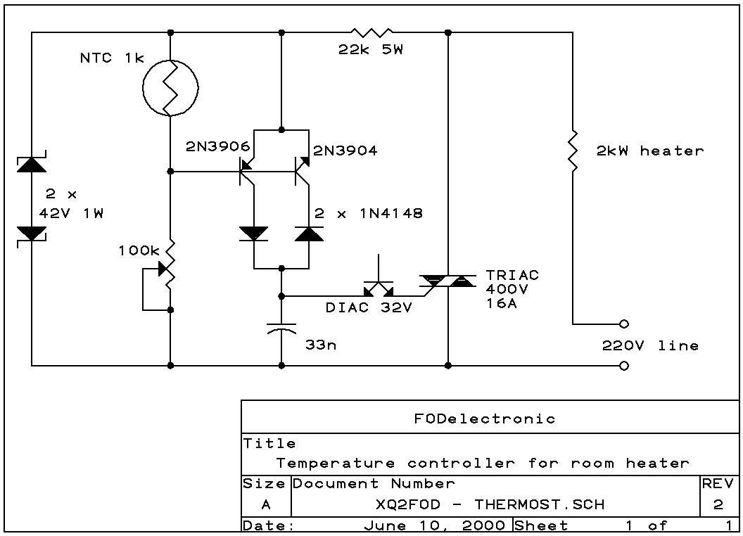
| Manfred's Simple Room Thermostat schematic |
This circuit would need to be modified slightly as it was designed around 220 V line voltage and it did not have RFI filtering. Also, there was no current limiting for the thermistor to reduce self-heating caused by excessive current flow. Finally, the circuit was designed for maintaining a temperature around 70 degrees F and I needed one for 105 degrees F. This circuit would be very easy to modify and I would be able to use all the components that came with the light dimmer I had purchased.
How the circuit works
Manfred did a very good job of explaining how the circuit works. You can see his explanation here. I will explain the changes I made.
I wanted to use as many parts from the dimmer control possible. The dimmer had a 250 K ohm variable resistor and two capacitors. The one used for the time constant was 0.068 uF and the RFI filter was 0.047 uF. The dimmer DIAC (part of the TRIAC) was triggered at 40 V rather than 32 V. I didnt think this would be a problem. Finally, I already had some 10 K ohm thermistors I wanted to use. These parts were then substituted for the ones Manfred had in his circuit.
One of my modifications was to add a current limiting resistor for the thermistor. According to the thermistor data sheet, I needed to limit the current to less than 380 uA. I originally chose to put a 300 K ohm resistor in series with the variable resistor. After testing, I discovered this value allowed a maximum temperature of about 104 degrees. It would have worked, but I wanted the 105 degrees to be closer to the center of the range of the variable resistor. To accomplish this, the resistor was changed to 220 K. Using this resistor, there is a 25 degree F temperature range from 95 to 120 degrees F and 105 degrees is pretty close to the center of the range. This resistor also limits the current through the thermistor to about 190 uA when the variable resistor is set at 0 ohms and the thermistor is at 5 K (105 degrees).
The RFI filter, L1 and C2 are the same as the dimmer. I just added them to the circuit.
How it was built
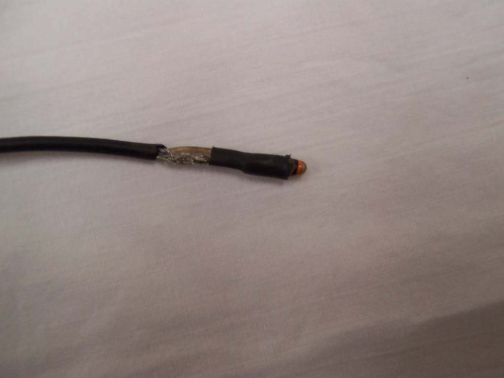
|
|
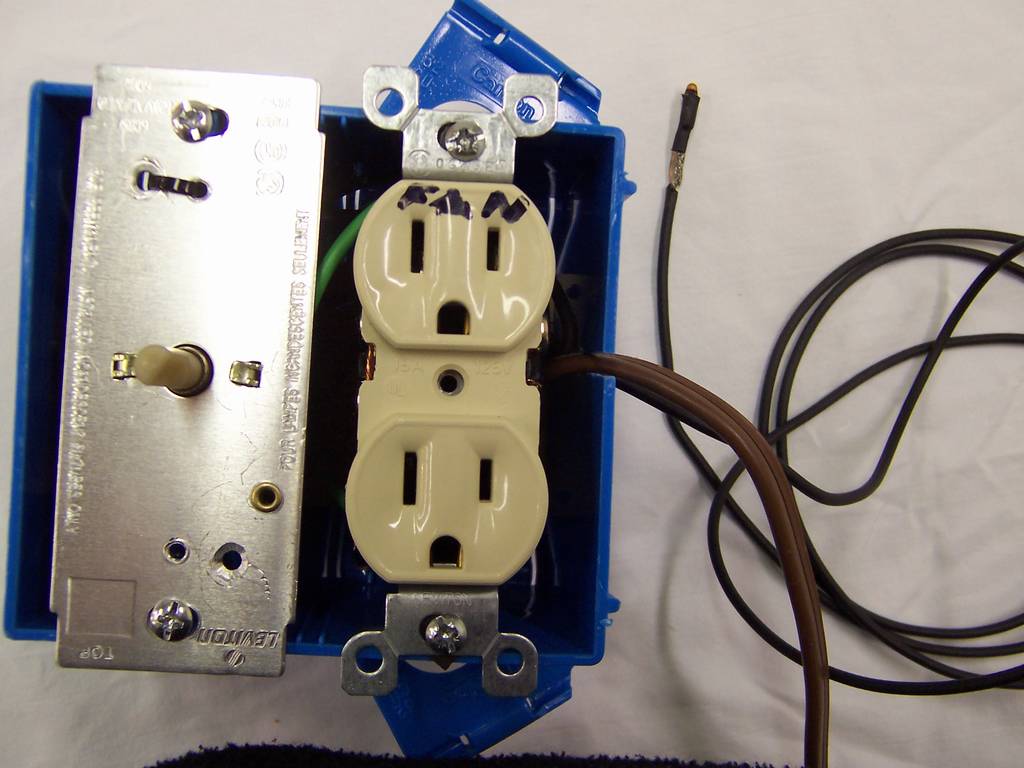
| Thermostat - ready to use | Close up of the thermister |
The case for the thermostat is a two gang plastic electrical outlet box. The light dimmer is mounted on one side and a standard power outlet on the other side. One of the sockets was used for the fan which runs all the time. The second socket is connected through the thermostat and used for the heating element (two 60 watt light bulbs). Total cost was under $10 USD since I could obtain all of the parts locally and did not have to pay for shipping.
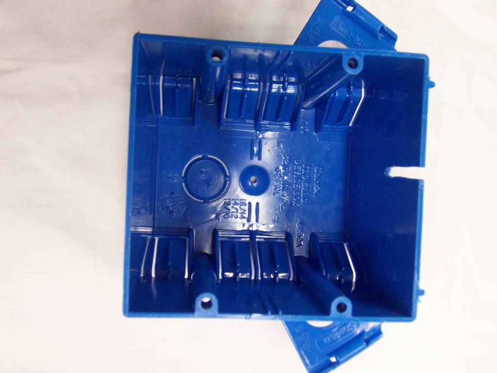
|
| The case is a 2-gang plastic outlet box |
First, I removed the plastic cover on the back of the dimmer. This was accomplished by drilling out the two rivets holding it to the metal cover. I then unsoldered the coil and the two capacitors. I left the TRIAC riveted to the metal cover as the cover is used as a heat sink. I also left the variable resistor attached to the metal cover. Next, I soldered three wires to the TRIAC and put shrink wrap over the leads and ran them to the circuit board. I also ran two wires from the variable resistor to the circuit board. I then mounted the coil and the two capacitors on the circuit board. The circuit board I used fit perfectly in the bottom of the two-gang plastic outlet box. Because of the way the box was made, the bottom of the board is about 1/4 inch off of the bottom of the box. The fit was so perfect, I only used one screw in the middle of the circuit board to hold it in place. Actually, I havent gotten around to putting a screw in. The wires from the circuit board to the dimmer control keep enough pressure on the board to hold it down.
The circuit was built on a strip board. Strip boards are very popular in Europe. They are not popular in the USA and are difficult to find. The one I used is from Futurlec, a mail order company with distribution centers in many parts of the world, including the USA. The price for the "STPBRD2" strip board is $1 and shipping is reasonable if you buy $16 worth of components. Strip boards have the traditional perf board layout with holes spaced every 0.1 inch. Each row of holes has a copper trace connecting them all together. This makes building the circuit very easy as the only wires you need to add are the vertical ones to connect the various rows together.
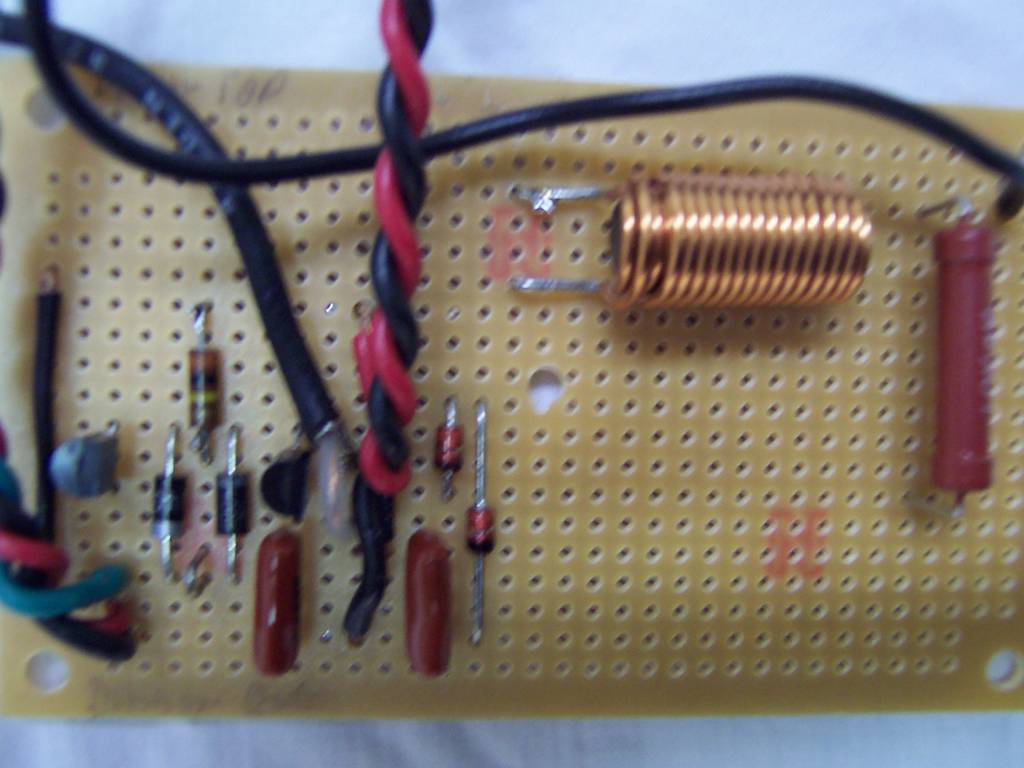
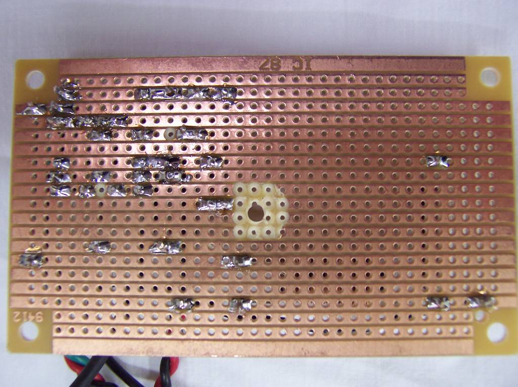
|
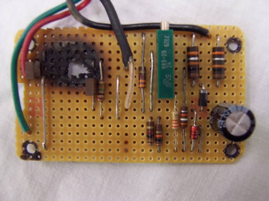
|
| Top of the strip board showing the components | Bottom of the strip board showing the copper traces |
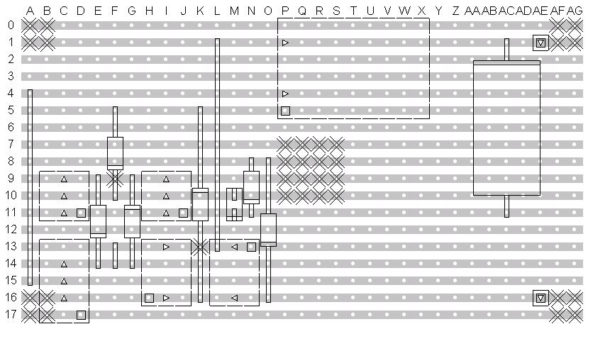
Below is the circuit layout. Note it is viewed from the top side of the board. The copper traces are on the bottom and are shown as gray horizontal lines in the background. The "X" denotes places where the copper trace is cut to separate connections on the left from those on the right. The straight lines, without components attached to them, are wires connecting two copper traces together. Triangles denote connections underneath components, such as transistors. A square or a band indicates pin 1.
Pin connections:
| Pin | TRIAC | Transistor | Diode/Zeners |
|---|---|---|---|
| 1 | MT1 | Emitter | Cathode |
| 2 | MT2 | Base | Anode |
| 3 | Gate | Collector |
Computer tools used
Schematic capture program: TinyCAD, free from http://tinycad.sourceforge.net/
(click here for hints on using TinyCAD)
Strip board layout program: VeeCAD; Free version: http://www.veecad.com/
Note: The free version of VeeCAD does not import component libraries. To transfer a component library from an existing schematic file to a new file, follow these steps:
- Start VeeCAD and create a new file for the schematic
- Save the file and exit VeeCAD
- Open a VeeCAD (*.per) file, which has a library in it, using a text editor
- Copy the "[Outlines]" and the "[LeadedOutlines]" sections
- Open the new file just created in VeeCAD
- Replace the "[Outlines]" and "[LeadedOutlines]" sections with the ones copied above
- Save the file
- Start VeeCAD and open the new file. Verify the outlines were transferred
Strip board layout (top view)
:
|
| Circuit Board Layout |
| Location | Component | Value | Description |
|---|---|---|---|
| C10 | Q1 | 2N3906 | General purpose PNP transistor (VCE >= 40 V) |
| C15 | Q3 | Q2010LT | TRIAC; Mounted off board. Markings on body: X25783. This device was part of the light dimmer. |
| E12 | D1 | 1N4002 | General purpose diode |
| F8 | R1 | 220K | 1/4 watt resistor |
| G12 | D2 | 1N4002 | General purpose diode |
| I10 | Q2 | 2N3904 | General purpose NPN transistor (VCE >= 40 V) |
| I15 | C1 | 0.068 uF | Capacitor; This device was part of the light dimmer. |
| K11 | R2 | 250K | Variable resistor; mounted off board. This device was part of the light dimmer. |
| M11 | TH1 | 10K | Thermistor (10 K ohm @ 25 degree C) |
| M15 | C2 | 0.047 uF | Capacitor; This device was part of the light dimmer. |
| N10 | Z1 | 1N4755 | 43 V; 1 watt; zener diode |
| O12 | Z2 | 1N4755 | 43 V; 1 watt zener diode |
| Q8 | Area used for mounting screw | ||
| T3 | L1 | 100 uH | Coil; This device was part of the light dimmer. |
| AC6 | R3 | 10 K | 1 watt resistor |
| AE1 | J2 | Black wire connection point to the load (light bulb) | |
| AE16 | J1 | Black wire connection point to the 120 V AC line cord (hot side). |
Sources for components:
Home Depot
| UPC # | Make & Model | Description | Price (Oct 2006) |
|---|---|---|---|
| 034481-100300 | B232A | 2-gang blue plastic outlet box | $1.01 |
| 078477-151273 | Leviton | 15A outlet | $0.49 |
| 078477-131954 | Leviton 6681-IW | Push on/off dimmer with RFI filter. Controls up to 600 Watts | $4.95 |
Futurlec
Most electronic stores should carry these devices
| QTY | Part number | Value | Description | Price |
|---|---|---|---|---|
| 1 | STPBRD2 | Small strip board (fits perfectly in bottom of 2-gang outlet box.) | $0.95 | |
| 1 | 2N3904 | 2N3904 | Q2; NPN general purpose transistor (VCE >= 40 V) | $0.10 |
| 1 | 2N3906 | 2N3906 | Q1; PNP general purpose transistor (VCE >= 40 V) | $0.10 |
| 2 | 1N4755 | Z1 & Z2; 43 V 1 watt zener | Not Available | |
| 2 | 1N4002 | 1N4002 | D1 & D2; General purpose diode | $0.05 |
| 1 | NTC10K | 10K@25 deg C | TH1; Thermistor | $0.35 |
| 1 | R220K14W | 220 K | R1; 1/4 watt resistor; 10 in a package | $0.10 |
| 1 | R010K1W | 10 K | R3; 1 watt resistor | $0.40 |
| Shipping in USA | $4.00 | |||
| Total | $6.10 |
Radio Shack
Pricing is a bit higher, but most components can be found at a local Radio Shack store.
| QTY | Catalog number | Value | Description | Price |
|---|---|---|---|---|
| 1 | 276-2016 | 2N3904 | Q2; NPN general purpose transistor (VCE >= 40 V) | $0.69 |
| 1 | 276-1604 | 2N3906 | Q1; PNP general purpose transistor (VCE >= 40 V) (15 transistors in a package) | $2.59 |
| 2 | 1N4755 | Z1 & Z2; 43 V 1 watt zener | Not Available | |
| 2 | 276-1653 | 1N4002 | D1 & D2; General purpose diode; 25 in a package. | $2.59 |
| 1 | 10K@25 deg C | TH1; Thermistor | Not Available | |
| 1 | 271-1132 | 220 K | R1; 1/2 watt resistor; 5 in a package | $0.99 |
| 1 | 10 K | R3; 1 watt resistor |
The 43 V zener diode seem to be a little hard to find. I live in Silicon Valley and just went to a local surplus store. They had a selection of about 100 different voltages. Other sources may be Jameco and Digikey.
Second Version
Circuit:
|
| Light dimmer circuit |
After the first version died (see story below), I thought about replacing the TRIAC with a larger one that could handle the current. However, there were several items about the circuit I did not like:
- Too complex
- Heating elements were either on or off as opposed to being of a variable intensity
- When the TRIAC was enabled, there would be a 1 or 2 millisecond burst of high frequency interference generated
- The components were difficult to find, having to go to multiple sources to get them
With these in mind, I sat back and thought about how I could improve the design.
After thinking for awhile, I hit upon the idea of using a cheap light dimmer. I went to Home Depot and found one for $5. Eureka! Lets see what this can do. I increased the dimmer setting until the temperature stabilized at 105 degrees F. Over the next several days, I monitored the temperature. Not surprisingly, the temperature varied with the ambient temperature of the room. Since this was a particularly chilly week, the temperature varied about 30 degrees from daytime highs to night time lows. This was unacceptable, I had to come up with a better solution.
I then got curious and wanted to see how they could build and sell a dimmer so cheaply. When I took the cover off, I was surprised to see there were only 5 components! I traced out the circuit; however, I did not know the pin out of the X25783 TRIAC. I searched the Internet, but couldnt find a pin out. So, I started looking at the datasheets for many other TRIACs and it appeared the TRIAC pin out was standardized for the TO-220 package. Now that I knew the pin out, I could complete the schematic.
Next, I searched for dimmer schematics. I found a bunch and surprisingly, they were all the same as the schematic for this dimmer. So, I felt comfortable with the schematic I had drawn.
Now that I had the schematic, I started researching how to add a temperature compensation circuit to this design. This led me to the third design which was described previously (see above).
How the dimmer circuit works
The TRIAC is a three terminal device and can be thought of as a switch. When the gate terminal reaches 40 V, the switch turns on allowing current to flow between the MT1 and MT2 terminals. To turn a TRIAC off, the current flow through it (independent of the gate voltage) must stop, which happens 120 times a second when using AC line power in the USA. To turn it on again, the gate must again be brought to 40 V and the cycle repeats.
Each half-cycle of the AC line voltage lasts for 8 milliseconds (ms). If the light bulb is turned on for the entire 8 ms it will be at maximum brightness. If the light is only turned on for 4 ms, then it will be noticeably dimmer. If the light is on for only 1 ms, it will be a faint glow.
The variable resistor, R2, and the Capacitor, C1, form an RC time constant. In one time constant period, the capacitor will charge to about 66 % of the maximum voltage available. During each half-cycle of AC line voltage, in the USA, this is about 60 V (120 V divided by 2). So, it will take just slightly longer than one time constant to charge to 40 V. The capacitor will take (resistor value times the capacitance value) seconds per time constant. The amount of time it takes is dependant on the setting of the variable resistor. When the capacitor charges to 40 volts, the gate lead of the TRIAC will also be at 40 V and the TRIAC will turn on. The longer it takes the capacitor to charge, the longer it takes for the light to come on. As mentioned above, the amount of time the light is on will determine its brilliance.
The remaining two components, L1 and C1 are used to filter the turn on spike caused by the TRIAC turning on. Both the inductor, L1 and capacitor, C1, are waiting for the spike. As soon as it occurs, they absorb the current and release it slowly, thus reducing RFI noise which would otherwise be generated.
First design
To control the temperature inside the hot box, I designed a simple thermostat. Since I was planning on using two 60 watt light bulbs, I knew the current would be about 1 amp. So I bought some 2 amp TRIACs. However, I also bought a 1 amp TRIAC as it was in a TO-92 package which is a lot smaller than the 2 amp TRIACs in a TO-220 package. I thought I would try it and see what happened. Well the TRIAC was under rated as the cold "on" resistance of the light bulbs is very low, so for a short period of time, much more than 1-amp would be needed from the TRIAC. After a couple of weeks of working successfully, the TRIAC shorted internally and applied 110 Volts to the 10 Volt comparator IC. As you can imagine, exciting things happened! Here is a picture after I cleaned the board. The IC got so hot, it burned a holed in the PC board!
|
| Thermostat circuit board after failure Note burned area at the top left |
Theory of operation of thermostat
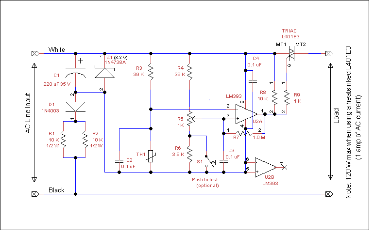
|
| Thermostat schematic |
Purpose:
This project was designed to be a thermostat to control an epoxy hot box. The epoxy needs to be kept at about 105 degrees F so it will be viscous enough to be easily mixed and absorbed by the fiberglass cloth.
A search for a suitable thermostat did not yield any within a reasonable price range. This one was designed to meet that need. The components used are readily available (in 2006) and the cost for them is about $5.
How it works:
Power supply
C1, Z1, D1, R1 and R2 comprise a low voltage, low current (< 15 mA) negative power supply. The low voltage is set at minus 8.2 V, though it could have been set at any voltage between 2.7 volts and 10 volts. However, if the voltage is changed, then the resistors used for the reference voltage for the comparator will need to be recalculated. The reference voltage is critical as described below.
I chose to use two resistors, R1 and R2, in parallel rather than a single resistor. As designed, a single resistor would have to be 1 watt. I didnt have any 1 watt, 5 K ohm resistors, so I used two 1/2 watt, 10K ohm resistors in parallel. Of course, a single 5 K ohm 1 watt resistor could be used.
A negative supply was chosen as the TRIAC works best and has the lowest gate current when operated in quadrants II and III (see the TRIAC datasheet). Quadrants II & III are when the gate being pulled negative to turn the TRIAC on. Quadrants I & IV are when the gate is pulled positive to turn on the TRIAC. Quadrant IV is the least desirable to used as it is the slowest and requires the most current.
The total current draw for the control circuit is less than 3 milliamps. This should be well within the capability of the power supply.
Temperature sensor
The temperature sensor is a 10 K thermistor. The "10 K" means at 25 degrees C, the resistance of the thermistor is 10 K ohms. This device is not critical and just about any thermistor could be used.
At 105 degrees F, the thermistor will have a resistance of about 5 K ohm. The max current through the device needs to be limited to less than 460 uA to prevent self-heating of the device from affecting the temperature reading. Both of these values came from a data sheet for the thermistor.
The thermistor, TH1 and R3 form a voltage divider. This circuit needs to have less than 460 uA flowing through it. I chose to use a 39 K ohm resistor for R3:
I = E/R = 8.2 V/(39 K + 5 K) ohms= 8.2 V/ 44 K ohms = 186 uA
The current is low enough so self-heating of the thermistor will not occur. What is the voltage across the thermistor? This is important as it will determine what the reference voltage needs to be:
E = IR = 186 uA x 5 K = 0.931 volts
Check:
(5 K / (5 K + 39 K)) x 8.2 V = (5 K/44 K) x 8.2 volts = 0.1136 x 8.2 V = 0.931 volts
So the comparator needs a reference voltage of around 0.93 volts. This is not a precise number (even though it looks like one) as the resistance of the thermistor is not exactly 5 K ohms at 105 degrees. So the reference voltage will need to be adjustable.
Voltage Comparator (LM393)
The voltage comparator is another simple device. It simply compares the voltage on the positive (+) and negative (-) inputs. If the positive input is higher than the negative input, the output will be high (actually open collector). If the negative input is higher than the positive input, then the output will be low.
The thermistor is connected to the negative input of the comparator. A reference voltage is connected to the positive input. The reference voltage will be about 1 volt so the comparator will switch states at 105 degrees F.
Since it is difficult to design a circuit for exactly 1 V due to 10 % resistors come in limited values and due to tolerances in the circuit and since others may want a temperature other than 105 degrees, the reference voltage was designed to be adjustable between approximately 76 and 115 degrees F. This is with approximately 216 uA of current flowing through the resistors which is approximately 4,000 times the input current for the comparator.
The following table shows the relationship between the resistors and the temperature range. The values in bold are the ones I chose for the circuit:
The following table shows the relationship between the resistors and the temperature range. The values in bold are the ones I chose for the circuit:
| R1 | R2 | R3 | Current | Low temp | Hi Temp | Temp change |
|---|---|---|---|---|---|---|
| 15K | 500 | 1.8K | 473.9 uA | 77.5 | 120 | 42.5 |
| 15K | 1K | 1.8K | 460 uA | 73.2 | 156 | 82.8 |
| 39K | 1K | 3.9K | 186 uA | 55 | 88.7 | 33.7 |
| 39K | 1K | 4.7K | 183 uA | 79.2 | 112.1 | 32.9 |
| 33K | 1K | 3.9K | 216 uA | 75.9 | 114.8 | 38.9 |
| 33K | 1K | 4.7K | 211 uA | 103.1 | 141.3 | 38.2 |
The equations to derive the above table are:
I(total) = 8.2 V/(R1 + R2 + R3)
V(low) = I(total) x R3 or V(low) = (R3/(R1+R2+R3)) x 8.2 V
V(high) = I(total) x (R2 + R3) or V(high) = ((R2 + R3)/(R1+R2+R3)) x 8.2 V
Temp (low) = (V(low) 600 mV)/10 mV = degrees C
Temp (high) = (V(high) 600 mV)/10 mV = degrees C
The reference voltage is applied to the negative input. When the output of the temperature sensor is higher than the reference voltage, the output of the comparator will be high and the TRIAC will be turned off. As soon as the temperature sensor output goes lower than the reference voltage, the TRIAC will be turned on and the light bulbs in the epoxy box will be turned on, thus heating the box.
R5, R6 and R7 are used as feedback to provide hysteresis. This is simply a voltage divider calculated with the output of the temp sensor at 1 volt and the output of the comparator switched on and off. If off, the circuit is a 1 volt source connected through a 10K, 3.9M and 10K resistor chain to a supply which is at 8.2 volts. The part that is of interest is the voltage across R6 which should be 18.4 mV positive with respect to the sensor output.
With the output pulled low, the 1 volt source is connected to a 10 K and 3.9 M network to the ground reference of the comparator. This gives a 2.5 mV swing relative to the sensor output. The hysteresis is therefore 18.4 + 2.5 = 21 mV.
TRIAC (L4004L3 or T405-600-W)
The TRIAC is the key to the whole system. It is the device which controls power to the heater in the epoxy box. The heater is a couple of 60 Watt light bulbs. When the gate of the TRIAC is brought low, the device turns on, supplying power to the light bulbs which in turn heats the epoxy box.
This particular TRIAC has a sensitive gate; meaning only 5 mA of current is needed to turn it on. This is a key requirement as the current to turn it on is being supplied by the comparator, which can supply a guaranteed 6 mA, probably more, but only 6 mA is guaranteed. The key parameters in selecting this TRIAC are:
Igt = 5 mA or less
It (current through the device) = 2 A or greater
Vt (voltage across the device) = 200 V or higher
When the gate goes low, the TRIAC will turn on for ½ cycle of the 60 Hz line . When the voltage approaches 0 volts, the TRIAC will turn off and remain off for a small period of time, till the voltage crosses 0 volts and then becomes high enough that the AC current reaches the turn on value. When the voltage again approaches 0 volts, the device will turn off and remain off for a short period of time till again the current reaches the turn on value. This will continue as long as the gate is held low. When the gate goes high, the device will remain on until the voltage approaches 0 volts, then it will turn off and stay off.
One concern I have is the amount of RF interference this circuit will create. I have not done any zero crossing synchronization. If this were done, then the device would only turn on when the voltage were crossing zero volts and the current would be low. With this circuit, the gate can go low at any time during the AC voltage cycle, so the very first turn on could be at a time when the voltage and current are at maximum, thus causing a big turn on spike and generating a lot of interference. However, this only happens when the device first turns on. On subsequent cycles of the line voltage, the gate will already be low so the device will turn on at or around zero volts. I dont think this will be a problem. One burst of RF every few minutes should not be a problem.
How to use
Using the thermostat is pretty simple. A digital thermometer is used to set it up. Plug the AC line cord into the socket and the lamps in the epoxy box into the "load". The thermostat must be put into the epoxy box as the temperature sensor needs to be in the box. Center the potentiometer and let the temperature stabilize in the box for a few hours. Check the temperature of the digital thermometer. Adjust the potentiometer if the temperature is not correct. Wait a few hours to see what affect the change had. It will probably take a day or two before the temperature is correct.
Alternatively, you could measure the voltage at the center of the potentiometer with a DVM. For 105 degrees F, it should read 1.0056 volts. The biggest problem with this method is safety. Keep in mind there is 120 V at various locations on the circuit board, so it is easy to get a shock. Once the voltage is set, you will still need to monitor it and make very small adjustments to get it exactly where you want it.