Page updated on: February 27, 2008
March 5, 2008
Chapter 8 - Headrest, heat duct, sat belts and step
Chapter Overview
Making the shoulder support, seat belt installation hardpoints and the aft heat duct.
The head rests are also supposed to be made in this chapter. However, they are not installed until a later chapter. Since I have not yet decided what style headrests I would like to have and since I'll probably be making the front opening canopy, I have decided to not make the headrests at this time. They are easy to make and making them later will not affect the rest of the build.
Step 1 - Carving the foam pieces for the headrests and shoulder support
The cutting of the foam was very straight forward. The only change I made was to not cut out the headrests. I'm not sure how I'll make my headrests as I'm planning on having a front opening canopy. This may affect the head rest design. I'll leave them for a later time.
Cutting the foam for the headrests was very easy. The 45 degree angle cuts are made the same way as in chapter 4 for the seatback.
The plywood cut outs were very easy to make. The one change I made was to space them 11.5 inches apart, like several other builders. The plans rather emphatically state the need for them to be no more than 8.66 inches apart for safety reasons (prevents the body from slipping out of the shoulder belts). However, this means the headrests would need to be notched. Also, 8.66 inches seems like it would cause the seatbelts to rub on my neck. This would not be very comfortable during a long flight.
The plans also suggest the hinge for the side opening canopy be mounted at this time. Since I am going with a front opening canopy, I didn't install the hinge.
Step 2 - Glassing the inside surface for wet layup
Like so many other builders, I mounted the nutplates for the seatbelts inside the shoulder support after glassing the inside surfaces, but before mounting it on the seatback. I followed the suggestions in the chapter 8 FAQ on the CozyBuilders.org website.
I first riveted the nutplates to the aluminum plates as outlined in chapter 8, step 5. Next, I drilled holes through the plywood which was 5-minute epoxied into the foam for the shoulder support. Next, I "cut" holes in the fiberglass, before laying it up, for the bolts to go through. This was needed so the bolts could be used to hold the nut plates in place as the flox cured. The holes were cut in the fiberglass before I wet it out. Next, the fiberglass was put onto the inside of the shoulder support, making sure the holes in the fiberglass lined up with the holes in the plywood. Next, the fiberglass was wet out. I then waited until the fiberglass was "tacky", per the plans. Then, I floxed the nutplates, which were riveted to the aluminum plates, to the inside shoulder support. I then put the bolts through the top of the shoulder support into the nutplates. However, the nutplates are round at the top and an oval shape at the bottom. This is to provide a tight connection with the bolt so it is difficult for it to back out. I did not want to change this shape, so I only screwed the bolts in part way. Before, I put the bolts in, I had put a nut and a big washer on the bolt. Once the bolts were screwed in, I then tightened the nut to hold everything in place. Next, the shoulder support was floxed to the seatback and the rest of the fiberglass was wet out, again, per plans.
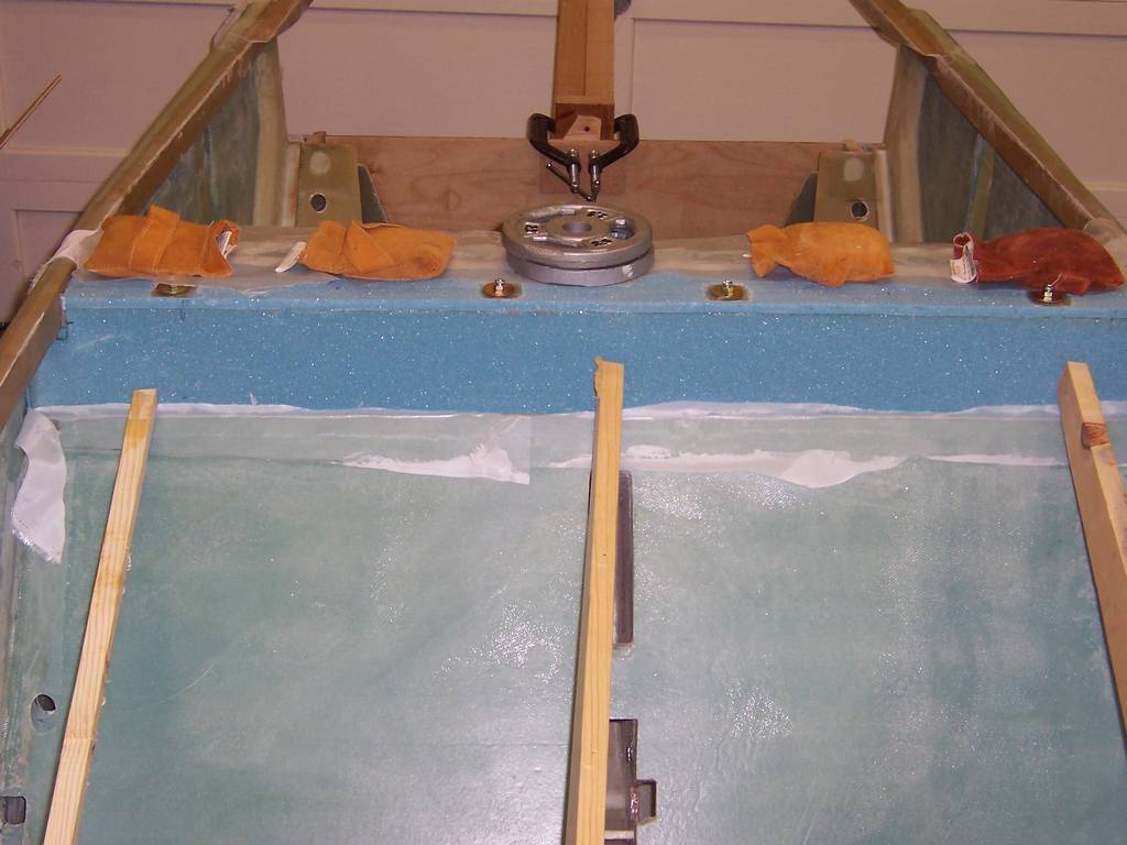
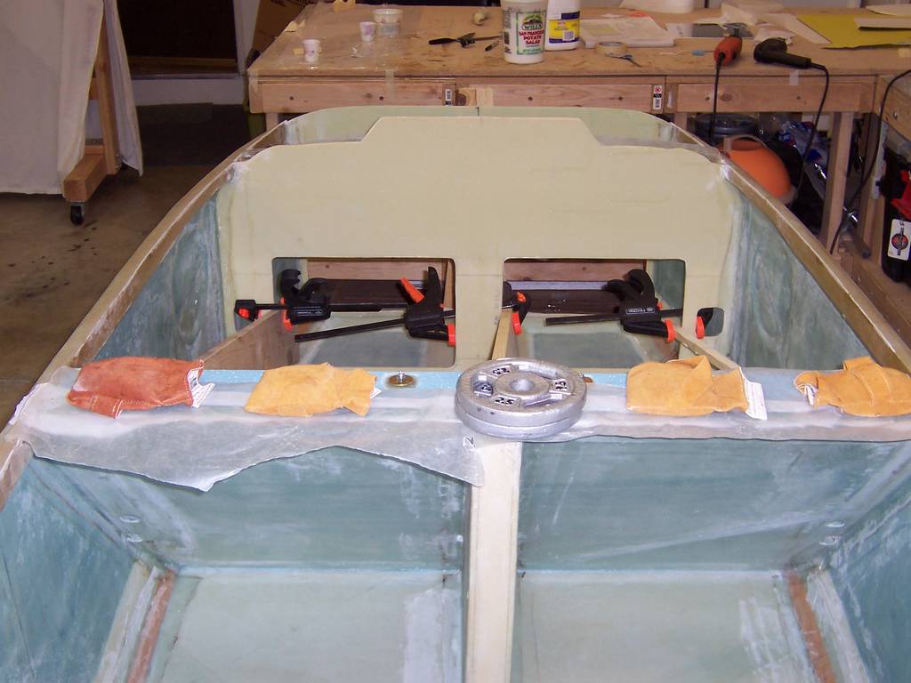
To keep every thing in place while it cured, I placed weights on top of the shoulder support and rigged up some boards to keep it from sliding down the front of the seat back. See the pictures below to see how this was done. I was very careful not to get flox or epoxy on the bolts.
|
|
| Weights and boards used to hold the shoulder support in place while it cured. | You can see how I used clamps to attach the boards holding the shoulder support in place. The boards are clamped to the leg cutouts of the instrument panel. |
|
|
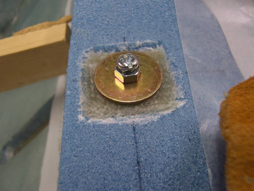
| This is a close up view of a bolt with the nut and washer in place. The bolt goes through the shoulder support and into the nutplate. This is needed to hold the nutplate in place while the flox for the nutplate cured. The bold does not extend all the through the nutplate as it is an oval shape at the bottom end. To apply tension on the nutplate, the nut shown in this picture was screwed down tight to firmly pull the nutplate against the bottom surface of the shoulder support. The washer is used to distribute the force on the top of the shoulder support. |
Step 3 - Glassing the outside of the shoulder support
Just a standard layup. Nothing special.
Step 4 - Glassing and installing the headrests
This step was skipped due to the use of a front opening canopy. I'll complete it later.
Step 5 - Installing shoulder harness attachments
This step was completed during step 2. By doing it early, it meant I did not have to make holes in the completed shoulder support to add the nutplates.
Step 6 - Installing the outside seat belt attachments and external step
These are the attachment points along the lower longerons for both the front and rear seats. The attachment points are pieces of 1/4 inch birch plywood which are shaped to conform to the shape of the lower longerons. They are then floxed in place and then a 7-layer fiberglass layup is placed over the plywood and extends onto both the sides and the floor.
Once the plywood supports are in place, metal brackets are then made for the seat belts to attach to. The brackets are made from angled aluminum about 2-inches long. One side is curved with a hole in the middle for the seatbelt. The other side has two holes drilled in it for bolts to attach it to the plywood supports and continue through the lower longeron. Once made, these brackets are floxed and bolted in place.
Step 7 - Center seat belt attach
The first sub-step was to make a template of the bottom of the fuselage. At this point, the bottom of the fuselage curves upwards. To make a nice tight fit, this curvature must be determined.
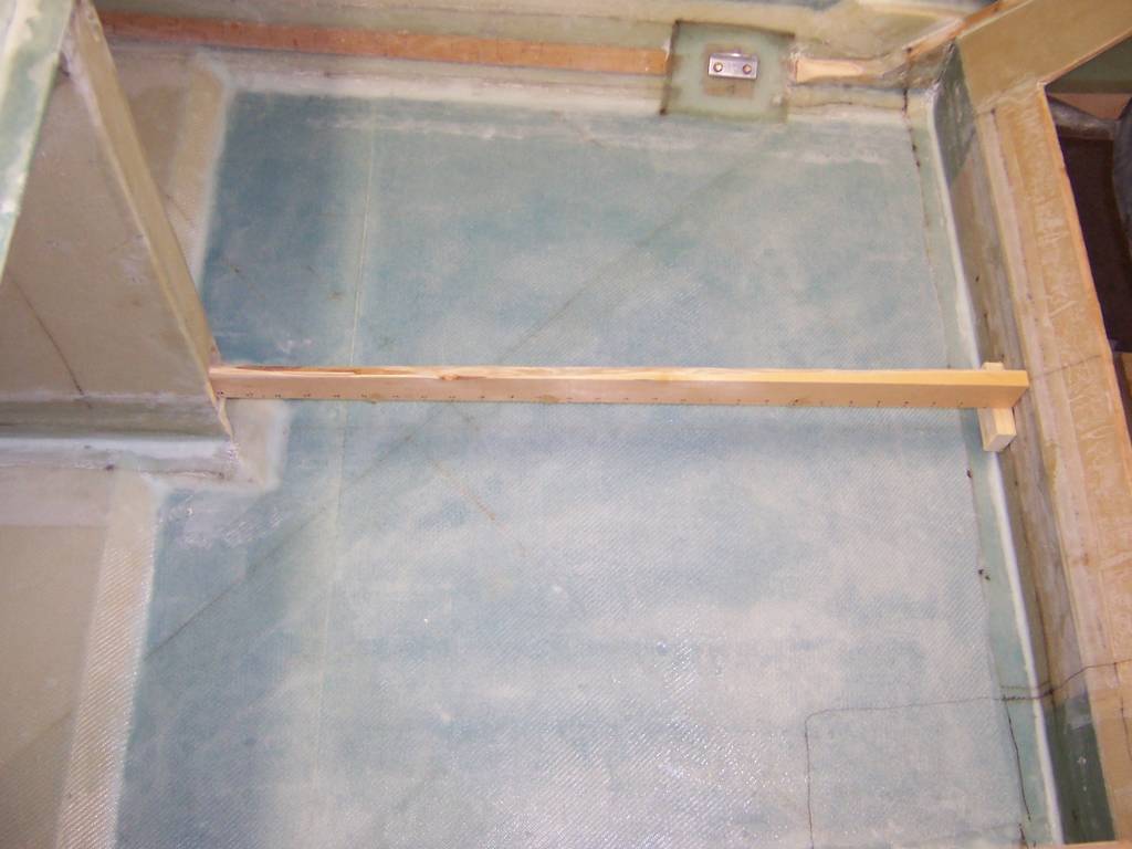
The plans specify making a paper template, however, this seemed like it would be difficult and time consuming to do. So, I took an idea from Wayne Hick's website. He temporarily installed a wood cleat on the forward landing gear bulkhead. He then placed a 2x4 from there to the aft end of the front heatduct. I used a 1 x 2 instead. The 1 x2 was small enough to rest on top of the aft end of the front heat duct, so I didn't have to make anything to hold it up at the heat duct. I then glued a cleat onto the aft landing gear bulkhead. The top of the cleat was 2 3/4 inches above the bottom of the fuselage. Next, a 1 x 2 straight piece of wood was used to bridge between the heat duct and the forward landing gear bulkhead. Measurements were then take at one inch intervals to determine the curvature. See the pictures below.
The measurements were then transferred to a piece of foam. The foam was cut out and the heat duct was assembled and floxed to the fuselage.
The transition piece is to adapt the square heat duct to a round tube which a hose may be attached to. The shape for the transition piece is easily made from urethane foam. I used Wayne Hick's suggestion to use electrical tape as a release agent to prevent the fiberglass from adhereing to the foam.
After the transition piece had cured and I had dug the foam out, it was floxed to the heat duct. To ensure a good strong attachment, I added some BID tape to cover the intersection of the transition piece to the heat duct, in addition to the flox called out in the plans. Once it had cured, I was impressed with how solid the attachment was. It is on their solid and I believe it would be very difficult to remove it!
The remainder of this step was done per-plans.
|
|
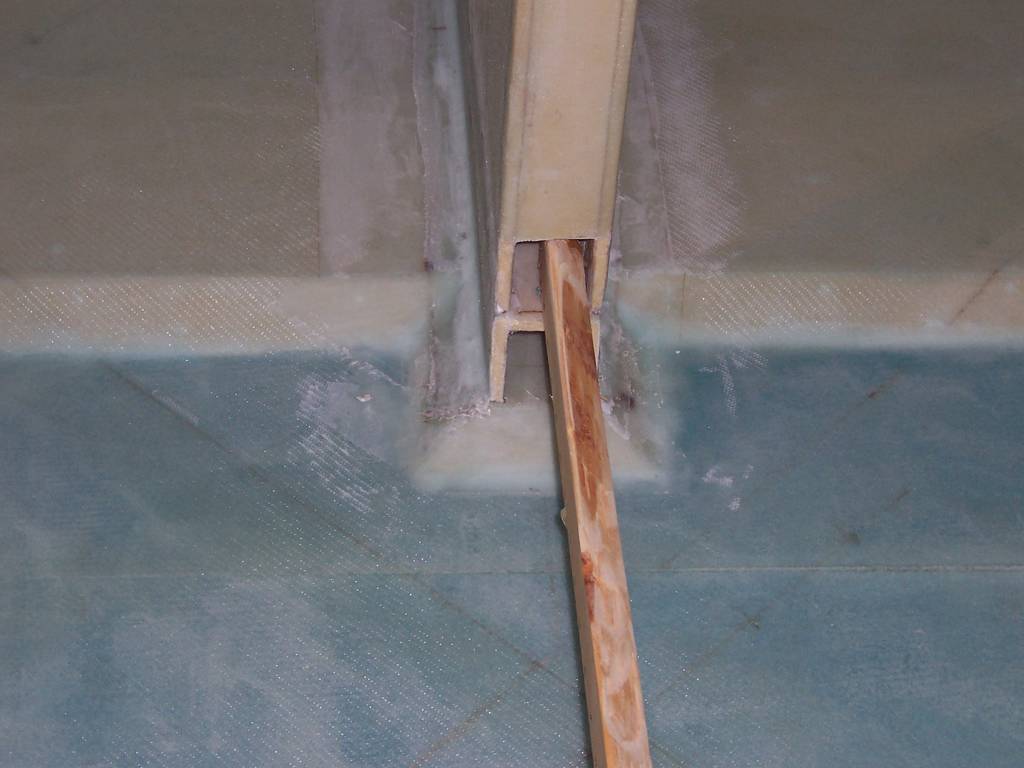
| Reference board in place. Note the cleat, which was hot melt glued onto the foward landing gear bulkhead, to hold the board in place. The top of the cleat is 2 1/4 inches above the bottom of the fuselage, as indicated in the plans for the width dimension of the aft end of the heat duct. | The forward end of reference board is slipped into the slot in the front seatback brace. |
|
|
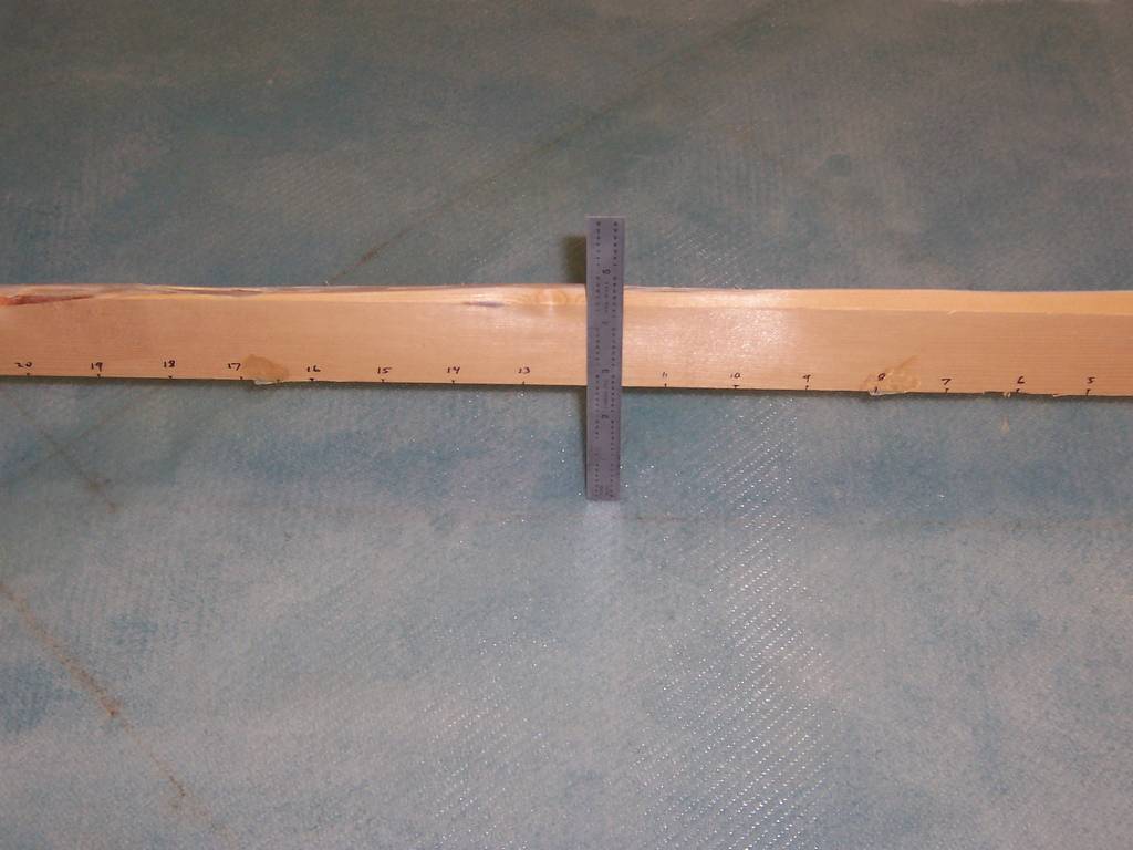
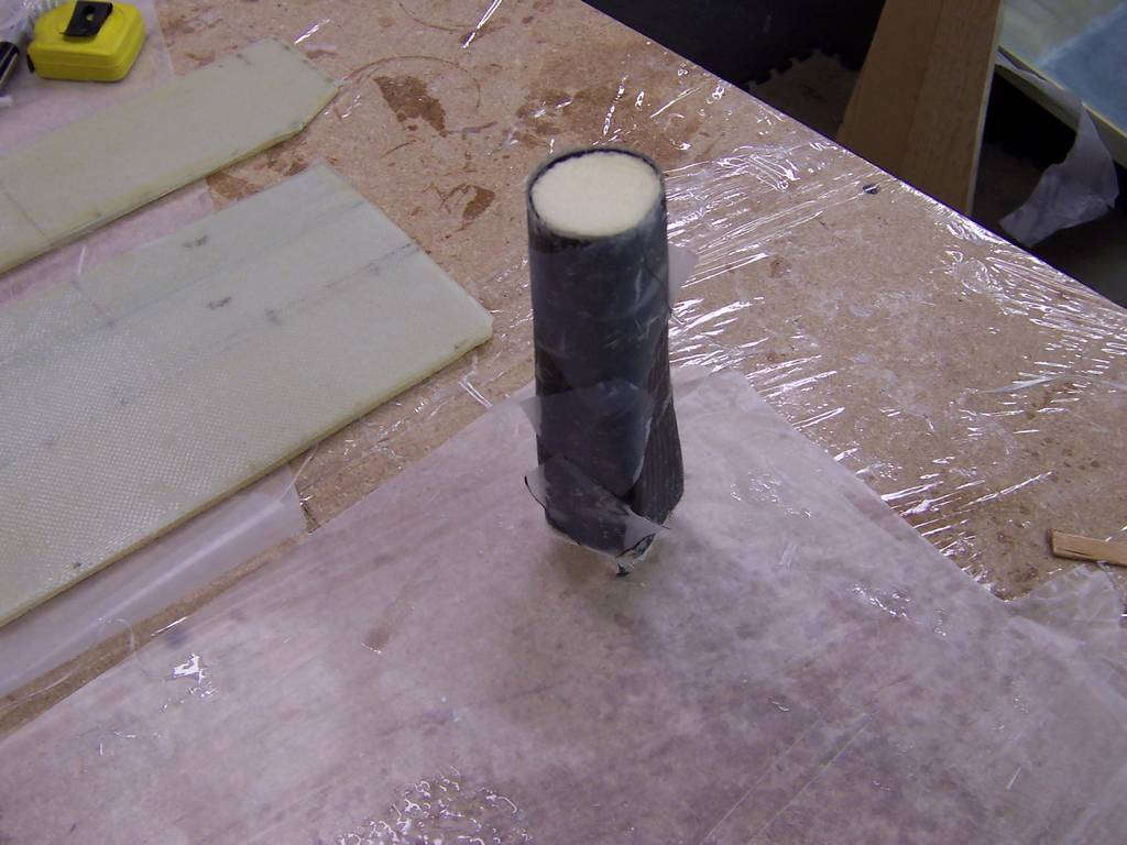
| Measurments were made between the bottom of the reference board and the fuselage bottom at 1 inch intervals. These were then transferred to the foam for the heat duct to get the proper shape of the heat duct to fit snuggly on the bottom of the fuselage. | The transition piece is curing. The urethane foam which was shaped to the dimensions specified can be seen on the top. The color is black because black electrical tape was wrapped on the outside of the foam before fiberglassing. The purpose of the tape is to keep the fiberglass from sticking to the foam. |
|

|
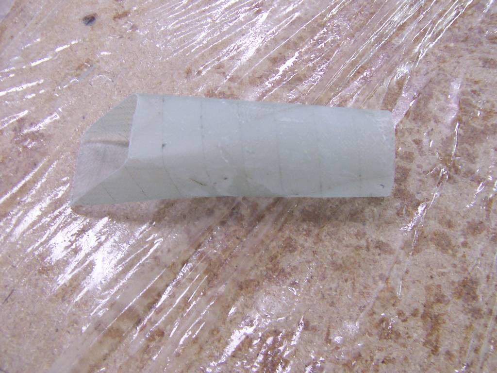
| The transition piece after the foam and electrical tape have been removed from the inside. Also, the 45 degree angle has been cut on the end which attaches to the heatduct. | The transition piece has been temporarily placed on the heatduct. |

|

|
| A side shot of the transition piece temporarily in place on the heat duct | Close-up shot. When permanently installed, there will be a uniform 1/4 inch gap between the transition piece and the end of the heatduct. |
Chapter Summary
A few photos of the plane at this stage to show what it looks like.

|
|
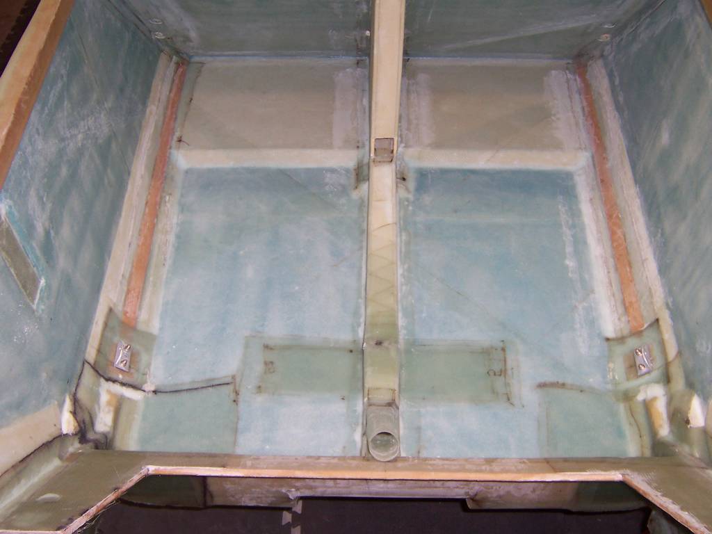
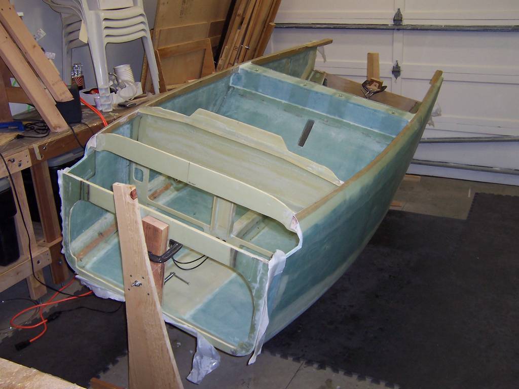
| Overall view of the fuselage looking aft. | Looking forward into the back seat area. This shows the back seat layups for the seat belt attach points. |
|
|
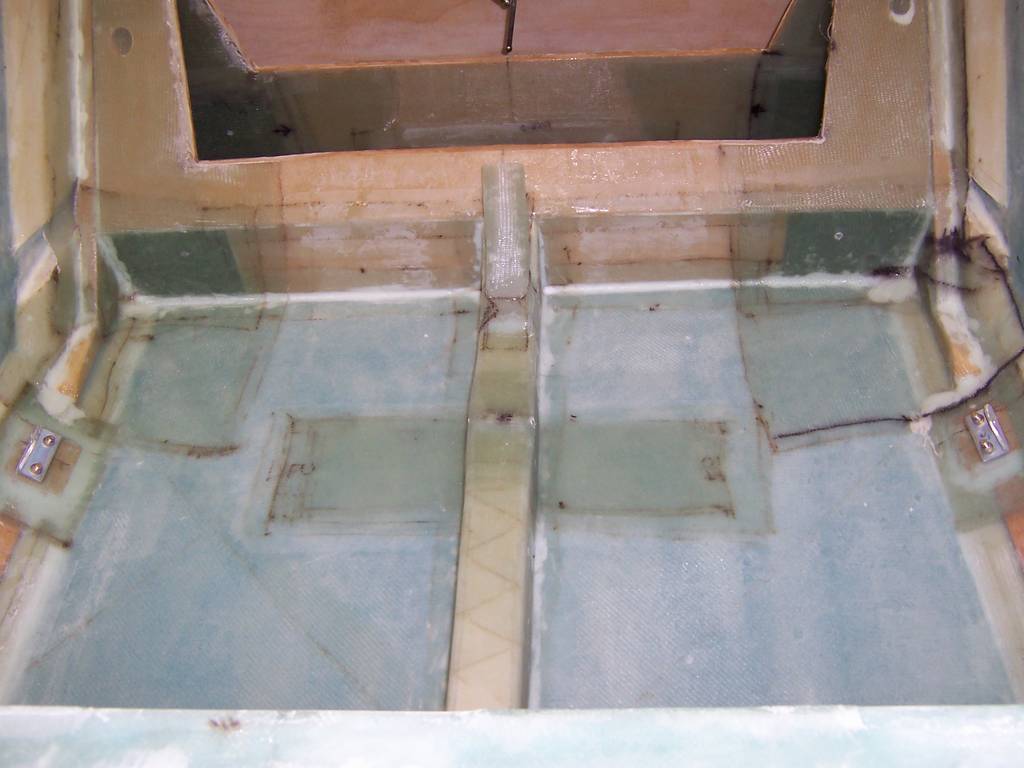
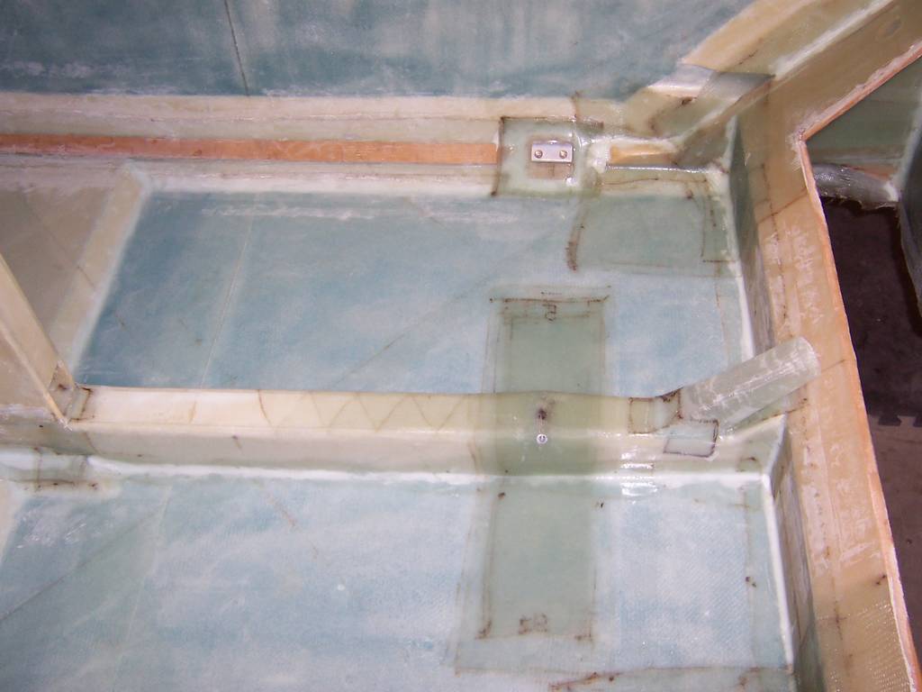
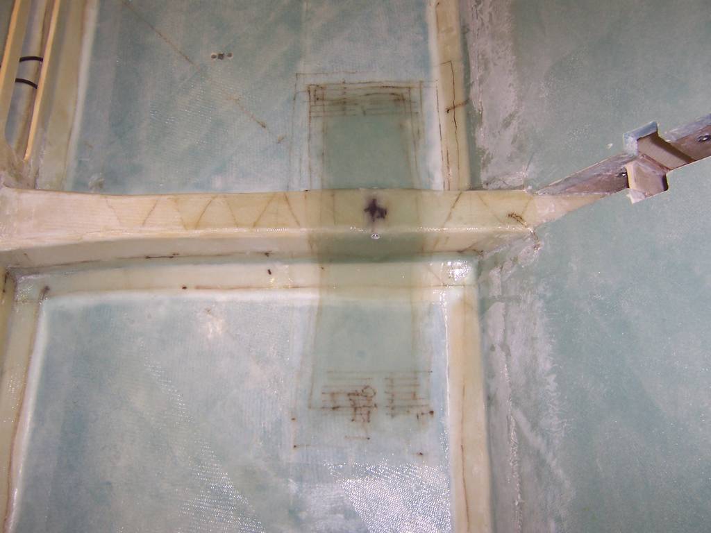
| Looking aft into the back seat area showing the three seatbelt attach points. | Side view, looking toward the right side, of the rear seat heat duct and seat belt attach points. |
|
|
| Overall view of the fuselage. | Side view of the front center seat belt attach point (looking toward the right hand side). |