Page updated on: December 1, 2007
December 29, 2007
January 24, 2008
Chapter 7 - Fuselage Exterior
Quick links within this page:
Step 1 - Building the NACA Scoop
Step 2 - Contouring the Bottom
Antenna Information
Step 3 - Fiberglassing the Bottom
Step 4 - Contouring the Sides
Step 5 - Fiberglassing the Sides
Chapter Overview
In this chapter I will finish the outside of the fuselage. I'll start out by building the flush, NACA scoop, then installing hard points for attachment of a landing gear door, tapering the sides back to the firewall, rounding the bottom comers, reinforcing the area where the step attaches, carving out the fuel sight gages, cutting out the area where the canard attaches, rounding the top comers, and lastly, glassing the outside skin. Up to now, the fuselage was a fragile, flexible weak box. After contouring and glassing, it will be an extremely stiff, strong, esthetically pleasing composite sandwich structure. Once this step is completed, the fuselage will look like it came out of a mold, but be considerably less expensive.
Step 1 - Building the NACA Scoop
The NACA scoop is on the underside of the plane. It is a specially designed airvent used to cool the engine. The advantage of NACA scoop is it will allow air to enter the engine compartment and yet creates only minimal drag. This is because the air trapped in the "groove" of the NACA scoop acts as a smooth surface on the bottom of the plane. The air entering the engine compartment pressurizes it. When the pressure becomes high enough that no more air can enter, the excess air follows the bottom curvature of the aircraft. This "spill over" effect minimizes the induced drag.
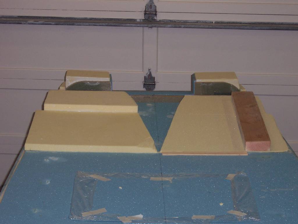
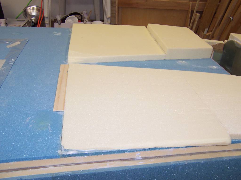
The building of the NACA scoop was very interesting. blocks of foam was placed on bottom in the shape of the scoop. This foam was then sanded using a long 2x4 piece of wood with sand paper attached to it. The sanding created a level surface from the landing brake to the top of the forward landing gear bulkhead.
The urethane foam sanded very easily. Unfortunately, this also caused deep gauges in the foam any time it was accidently nicked. I had to use a bit of micro to fill these gauges.
|
|
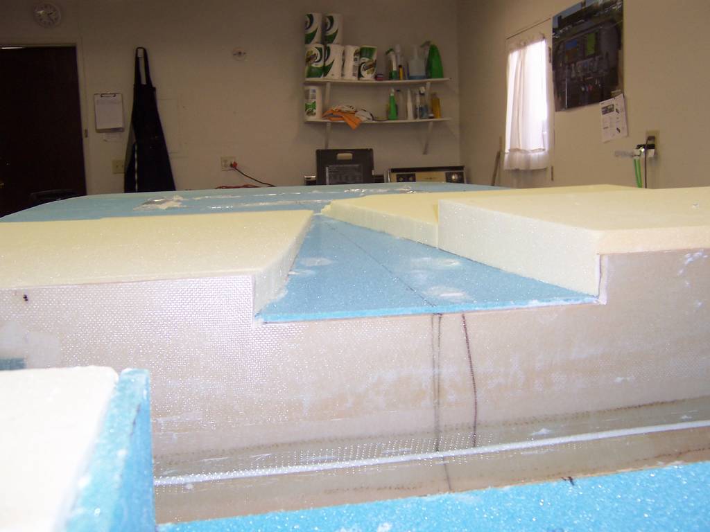
| Looking aft from the front of the plane. The left side shows what the foam looked like before it was sanded. The right side shows the sanded foam with the sanding block laying on top | Looking forward from the aft end of the plane. In this picture, the left side has been sanded and the right side has the blocks in place before sanding. |

|

|
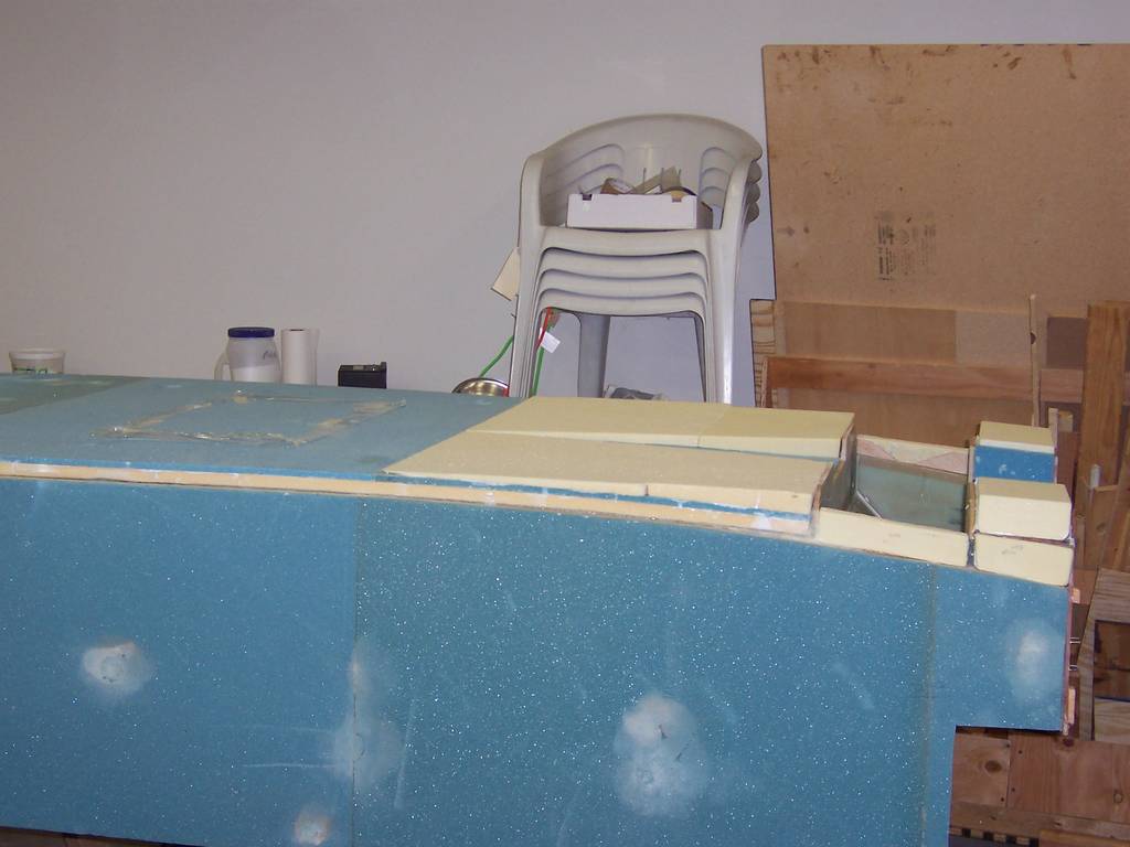
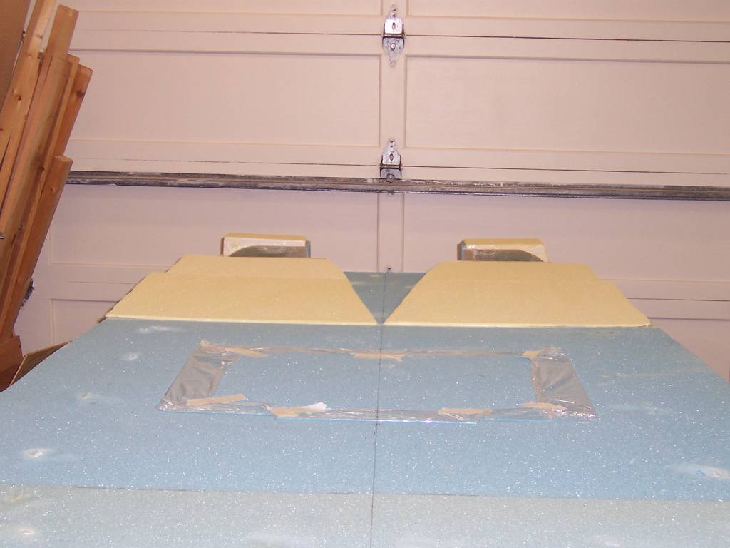
| Side view showing the foam for the NACA scoop. | This view shows both sides of the NACA scoop after sanding. |
|
|
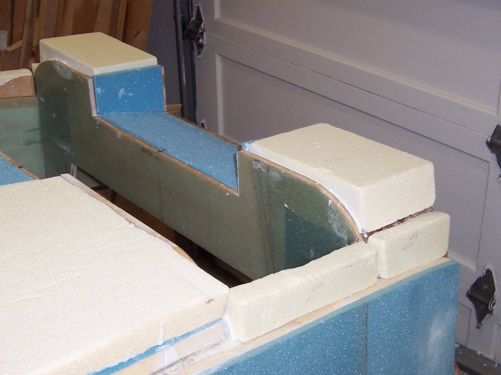
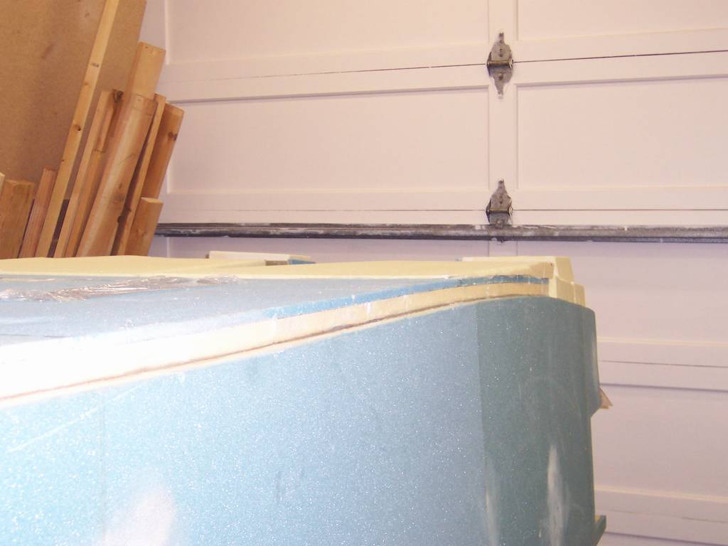
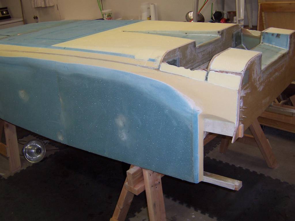
| Side view showing both sides of the NACA scoop after sanding. | Close up of the foam blocks, before sanding, used to shape the aft portion of the plane. |
|
|

|
|
Step 2 - Contouring the Bottom
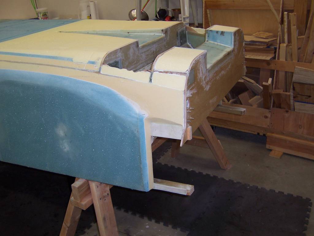
In this step, the bottom edges are sanded to curved shape. This was done using the Tim Lump fuselage carving tool.

|
|
| The aft blocks have been sanded to shape. | View of how the area for the spar is to be sanded. |
|

|
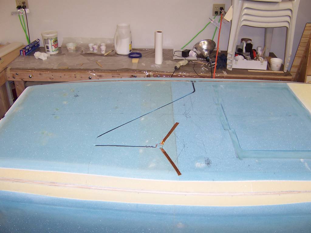
| Locations I chose for the marker beacon Antenna (long antenna) and the glide slope antenna |
Antenna Information
There has been a lot of discussion on the optimal place to put the various antennas on the plane. No matter where you put the antennas, there will be trade offs which need to be made. For me, I have chosen the following antennas and locations:
| Antenna | Antenna length (each arm) (in inches) |
Number of antennas | Copper tape needed |
Location |
|---|---|---|---|---|
| Marker beacon | 34.3" | 1 | 64.6" | Fuselage bottom |
| Glide slope | 7.5" | 1 | 15" | Fuselage bottom |
| VOR (navigation) | 22.8" | 2 | 91.2" | Wings |
| VHF communication | 20.3" | 2 | 81.2" | Rudders |
| 2M amateur radio | 17.7" | 2 | 70.8" | Canard |
Total | 322.8 inches |
There are two amateur radio 2M antennas. One will be used for the APRS packet radio tracking system. The other is for 2M voice communications. The tracking system will be connected to a GPS receiver. The radio will then send out position reports at regular intervals. These reports can be viewed by anyone on the Internet by going to the appropriate tracking service, such as FindU.com.
It seems no matter where you put the various antennas, there are trade offs to be made. The ones I made were to put the marker beacon on the pilot side of the plane. This has the trade-off of having the antenna very close to the metal step and just a few inches below the pilot and a couple of inches below the wiring channel. For the glide slope, the trade off is being near the marker beacon and just a few inches below the passenger seat. Neither of these locations is ideal. I'm fairly certain the antennas will function just fine as both of these antennas will be used when they are close to the transmitter at an airport. The navigation, communication and ham antennas will be used with stations much further away, so it is important they be in a more optimal location.
All of my antennas are homebrew. I purchased some 8-inch wide copper flashing from Home Depot. I cut it down to 1/2 inch strips using a bandsaw. Actually, this did not work out all that great as the width varies by about an 1/8 inch, but I don't think that will be a problem. I might have been able to be a bit more accurate using a hacksaw.
The coax is RG-58/U and was purchased from a local surplus shop, HSC Electronics (formerly Halted Specialties Company). I bought 200-feet to have enough for all of the antennas. I estimated it as follows:
| Antenna | Location | Length of COAX needed (in feet) |
Number of antennas | Total COAX needed (in feet) |
|---|---|---|---|---|
| Marker Beacon | Fuselage bottom | 9 | 1 | 9 |
| Glide slope | Fuselage bottom | 2 | 1 | 2 |
| VOR navigation | Wings | 20 | 2 | 40 |
| VHF communications | Rudders | 37 | 2 | 74 |
| 2M Ham | Canard | 6.5 | 2 | 13 |
| Excess behind IP | 6 | 8 | 48 | |
Total | 8 | 186 feet |
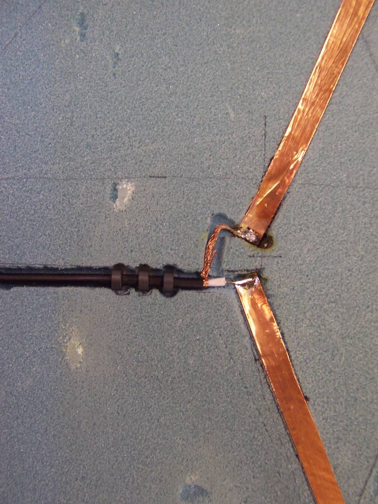
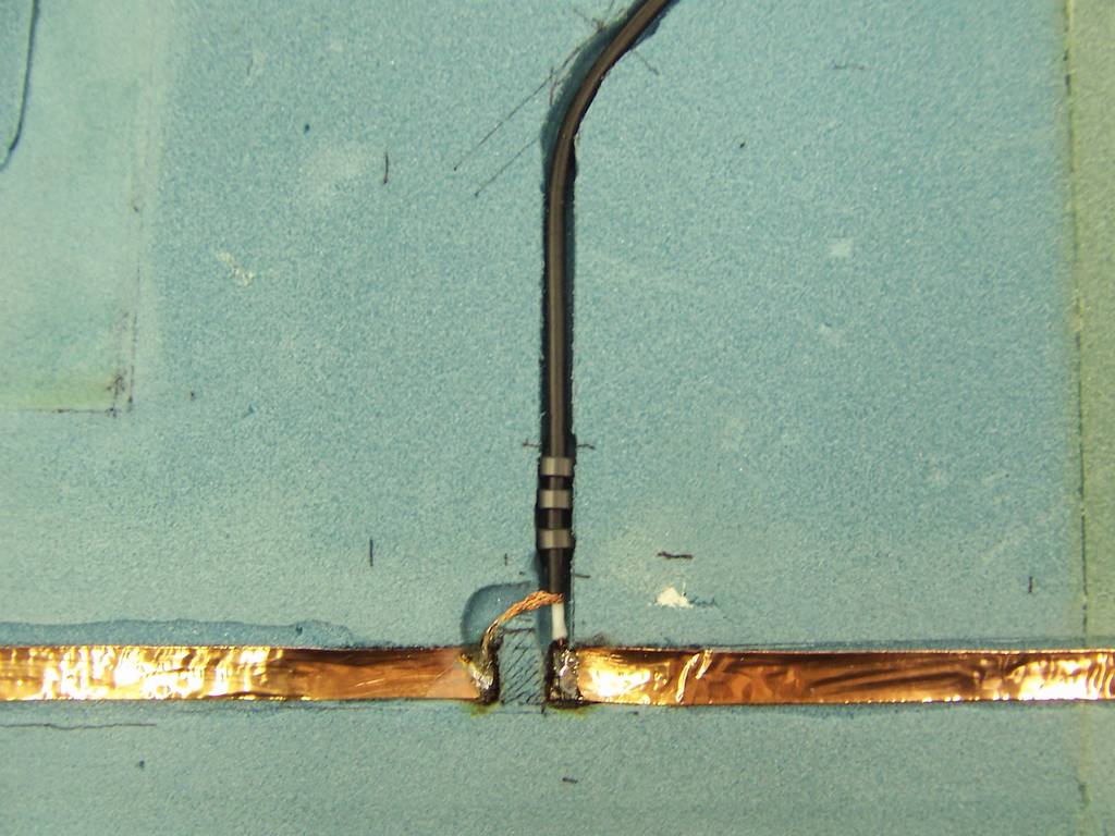
The actual construction of the antennas is shown in the following pictures. A dipole antenna, typically has both arms in a straight line. However, this will cause a null in the reception of signals perpendicular to the straight line. To reduce this null area, the arms are offset from a straight line by 10 to 30 degrees, thus forming a "V" shape. The only exceptions to this are the marker beacon and the VHF communications antennas.
The transmission line for a dipole antenna should be a balanced line for optimal performance. However, balanced lines are difficult work with. Instead, the antenna is fed with an unbalanced line, such as COAX. The disadvantage is the shield of the COAX will carry undesired current. To reduce this unbalanced current, three ferrite toroids are placed on the line near the connection to the antenna. However, not all ferrite toroids are designed to work at these frequencies. The toroids I am using is Amidon part number FB-43-2401.
|
|
| Location of the antennas. | Detail of the connections to the glide slope antenna |
|
|
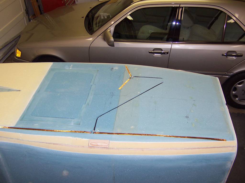
| Another shot of the location of the antennas. | Detail of the connections to the marker beacon antenna. |
|
|
| More pictures showing the contouring for the aft portion of the fuselage | Another contouring photo |
Step 3 - Fiberglassing the Bottom
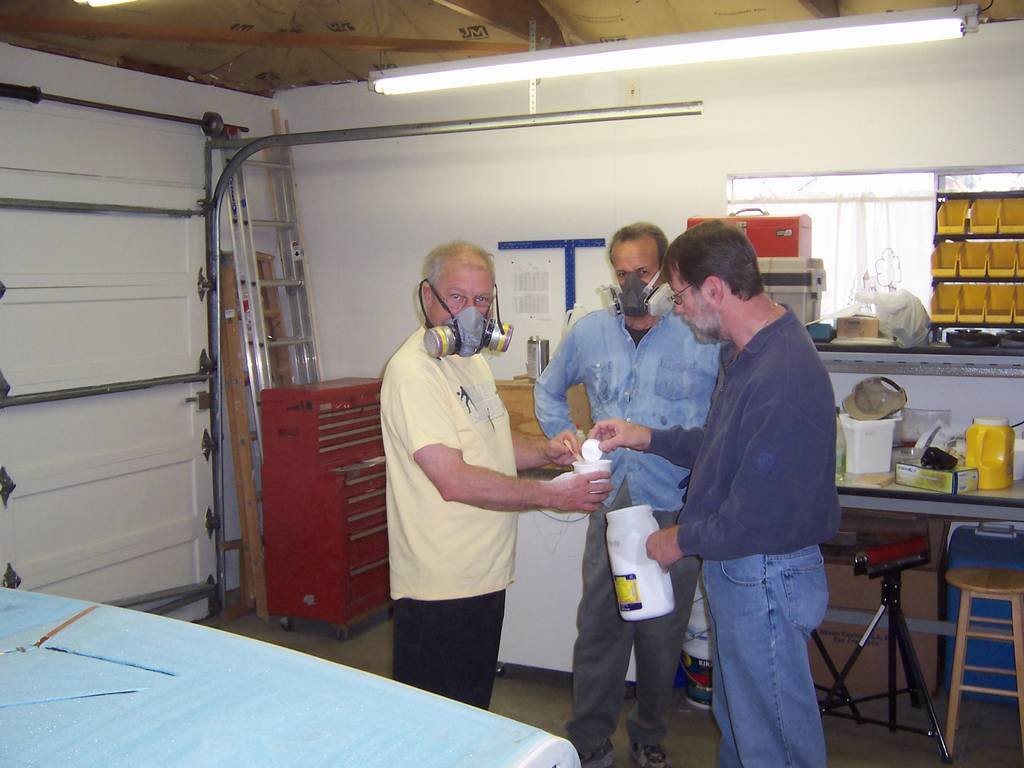
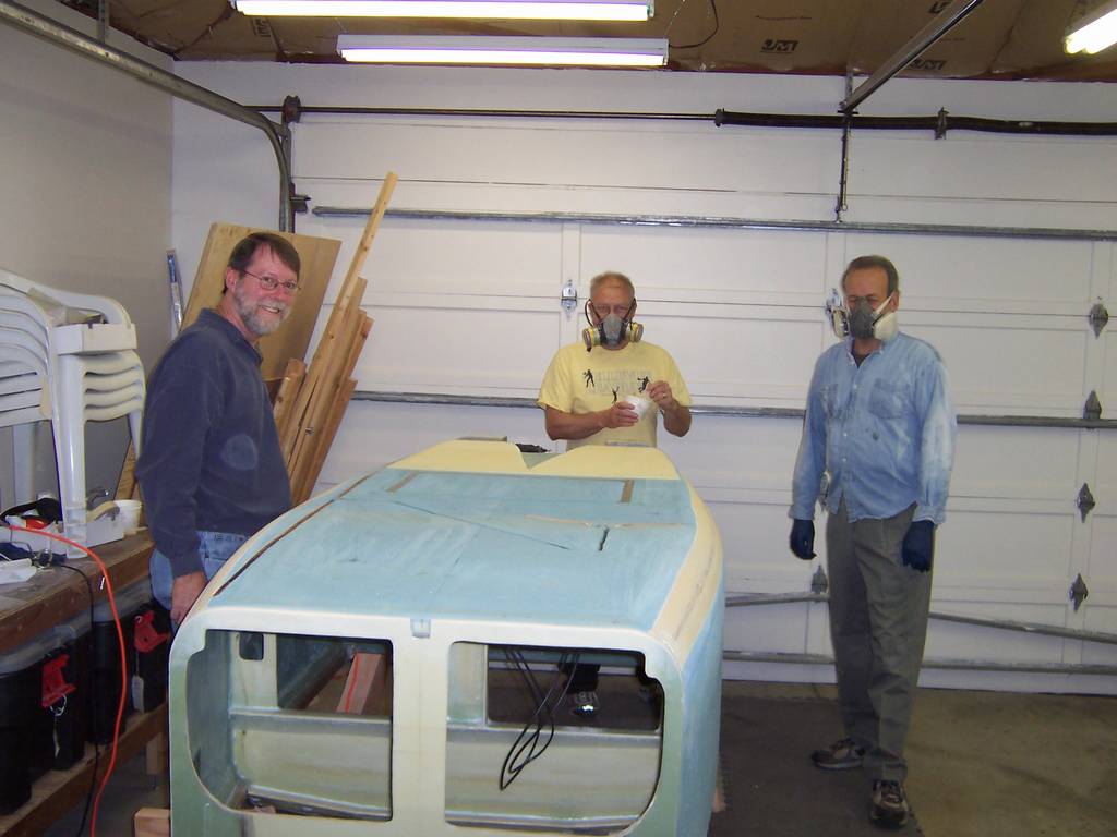
Finally, it is time to fiberglass the bottom! Ted, Neil and Jeff volunteered to come over to help with this large layup. It took about 6-hours from start to finish. It would have been quicker, but I was scrambling at the last minute and had not had a chance to cut the fiberglass, prepare the surface of the foam for applying the fiberglass or making the flox corners for the NACA scoop. So, a couple of hours was spent doing this prep work. However, it went well and I'm very pleased with the outcome.
The big layups sure go quicker when you have help. It is also a lot more fun and there is a sense comradre with all of us working together. I really appreciate all of the help I receive from local Cozy builders! Thank you very much for the support you give to me!
|
|
| Left to right: Ted, Neil and Jeff. Preparing to apply micro to the bottom in preparation for fiberglassing. | Left to right: Jeff (from Fremont), Ted (from Holister) and Neil (from Albany). |
Step 4 - Contouring the Sides
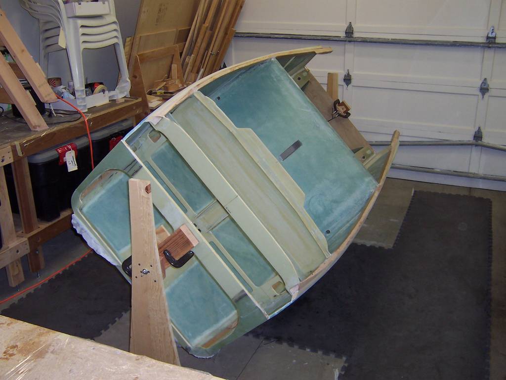
For me, the most exciting part of this step is turning the "tub" over so it is sitting right-side-up. It was really gratifying to finally be able to look down into the plane! If the sides had been fiberglassed and the landing gear attached, I would have jumped into it to make more airplane noises! Since there is a possibility of "denting" the fiberglass on the bottom where the saw horses support it, I thought I'd better wait. I did cover the saw horses with foam to keep the weight of the fuselage from forming a depression. I hop that is enough protection.
The first task is very daunting. You must cut a large piece from the forward part of the fuselage for the canard. I'm always nervous when I make big cuts like this and it ends up taking a lot longer than I thought it would. I do a lot reading and measuring multiple times to make sure I am doing it corrrectly. However, I won't know until I install the canard in chapter 12.
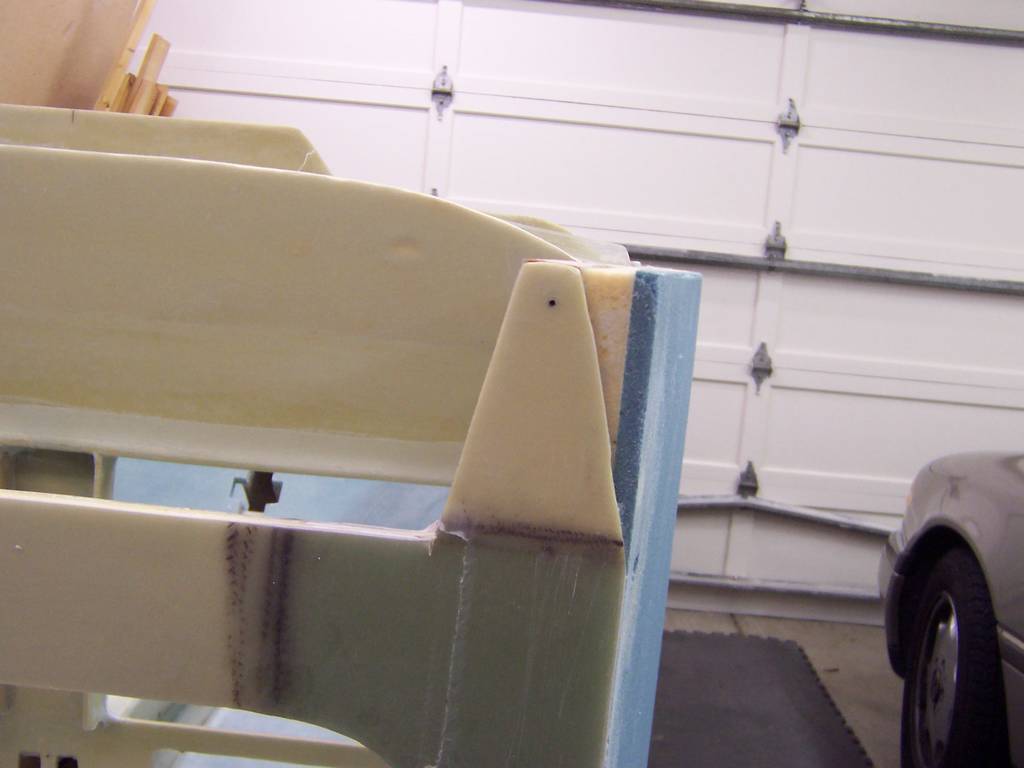
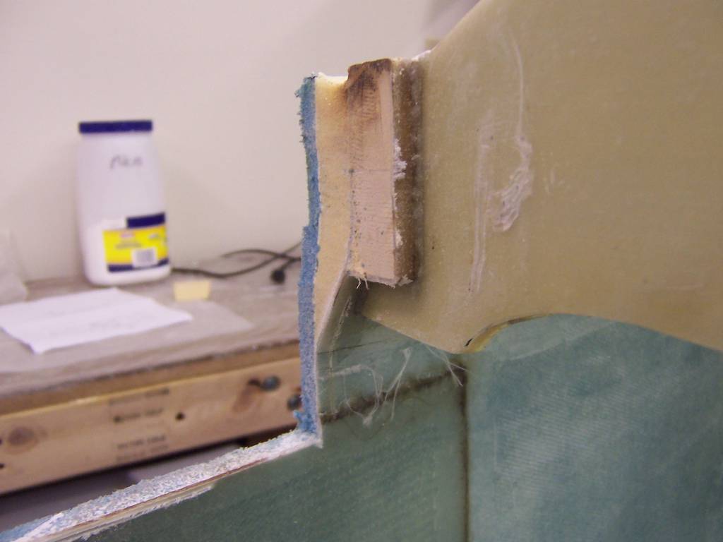
The next task is to shape the top of the fuselage sides. Below are a couple of pictures showing what it looks like before the shaping takes place.

|
|
| Left side of F22 before the tab was cut off. | Right side of F22 before the tab was cut off. |
|
|
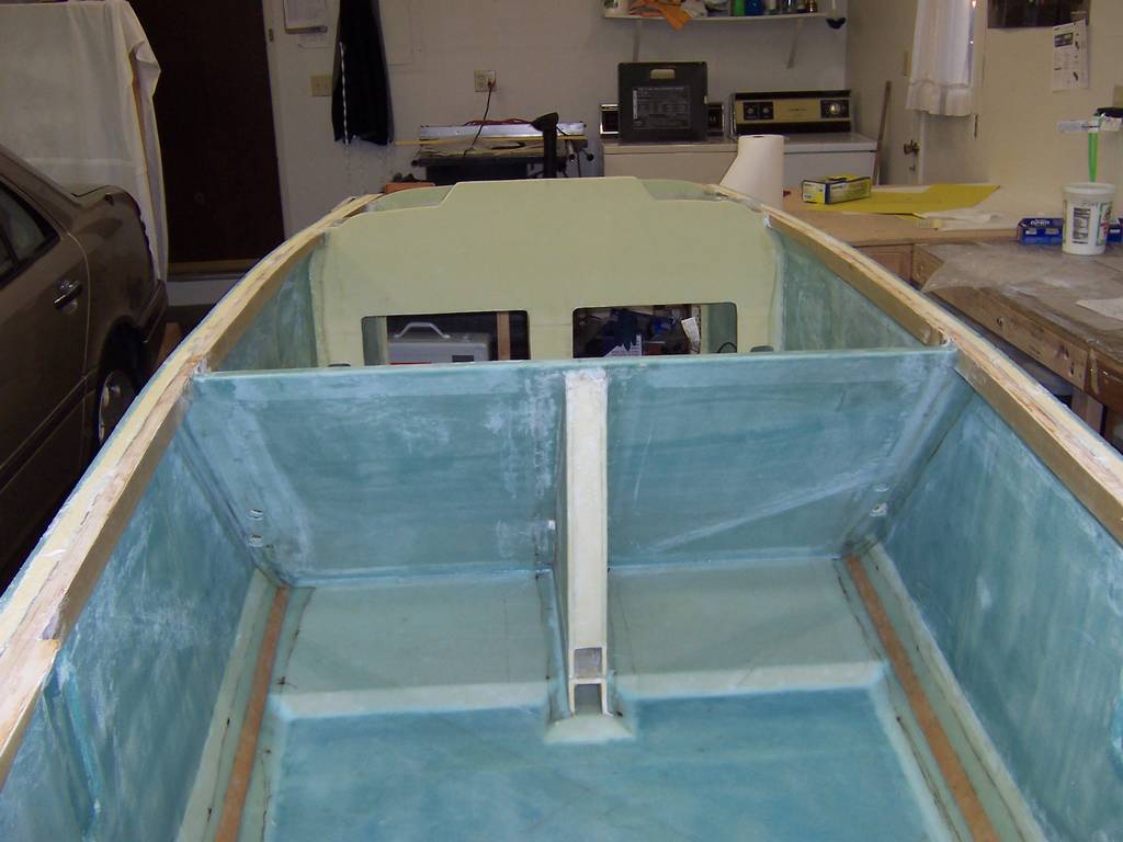
| Overall view from the rear, before shaping. | Overall view from the side, before shaping. |
|
|
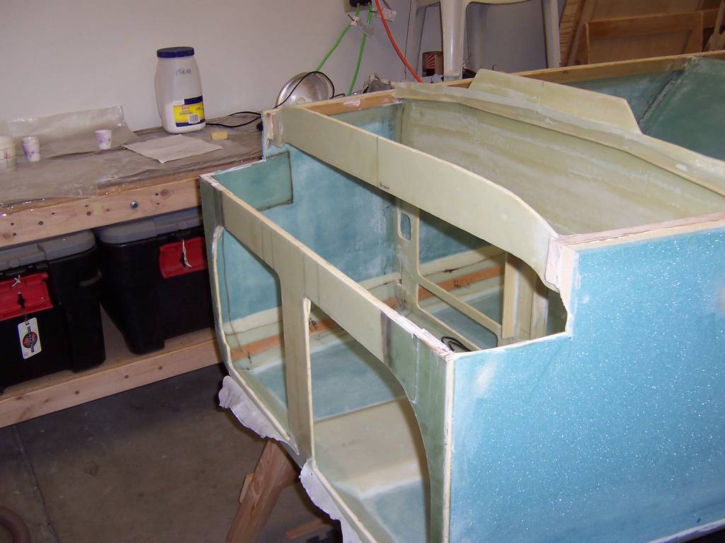
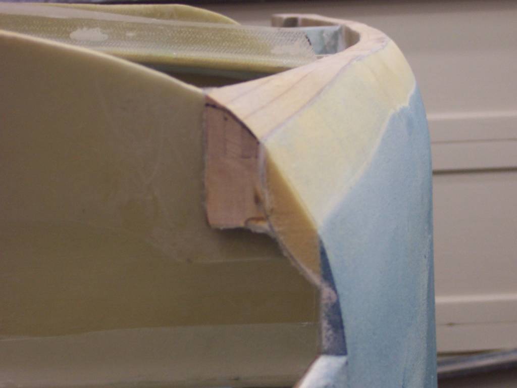
| View of F22 after the canard cut-out was made. | The plan says to cut out the portion from F28 to F22. Since I had moved F28 from the plans 5.9 inches aft of F22 to the general consensus position of 6.25 inches, I thought I would leave the extra 0.35 inches forward of F28 uncut. I can trim it later when I fit the canard in chapter 12. |

|

|
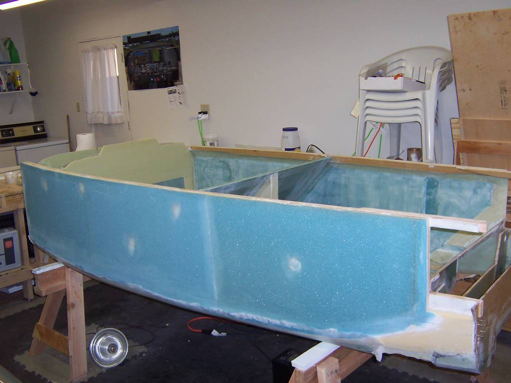
| This is a picture of what the left hand side looked liked like before contouring. | Right hand side before contouring. |

|
|
| Left hand side after contouring | Right hand side after contouring |

|
| Both sides after contouring |
Step 5 - Fiberglassing the Sides
Step 5 starts out making a rotisserie for the plane. This allows the fuselage to be rotated into different positions when fiberglassing the sides and the making the firewall reinforcements.
For some strange reason, making the rotisserie was more of a challenge than it should have been. I kept avoiding thinking about it. Finally, I started by taking small tiny steps. When that wasn't fruitful, I called my buddy Jeff over and he and I whipped it out in a couple of hours.
I didn't want to purchase any new lumber for something that was going to be temporary. So, I looked around to see what wood I had available. When I looked on the back patio, I saw the jigs for building the sides. Hmmmm, I wonder if they could be used for the rotisserie. I bet they could be cut so they could be angled like the 2x4s Nat shows on the plans.
When Jeff came over, I mentioned it to him. He took one look at them and said "I got an idea" he then went on to describe using them as they are and worrying about having them angled. The pictures below show how we built them.
|
|
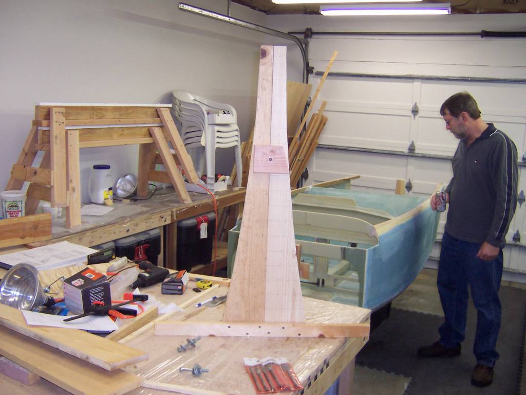
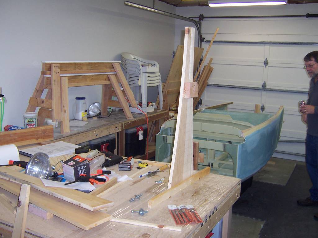
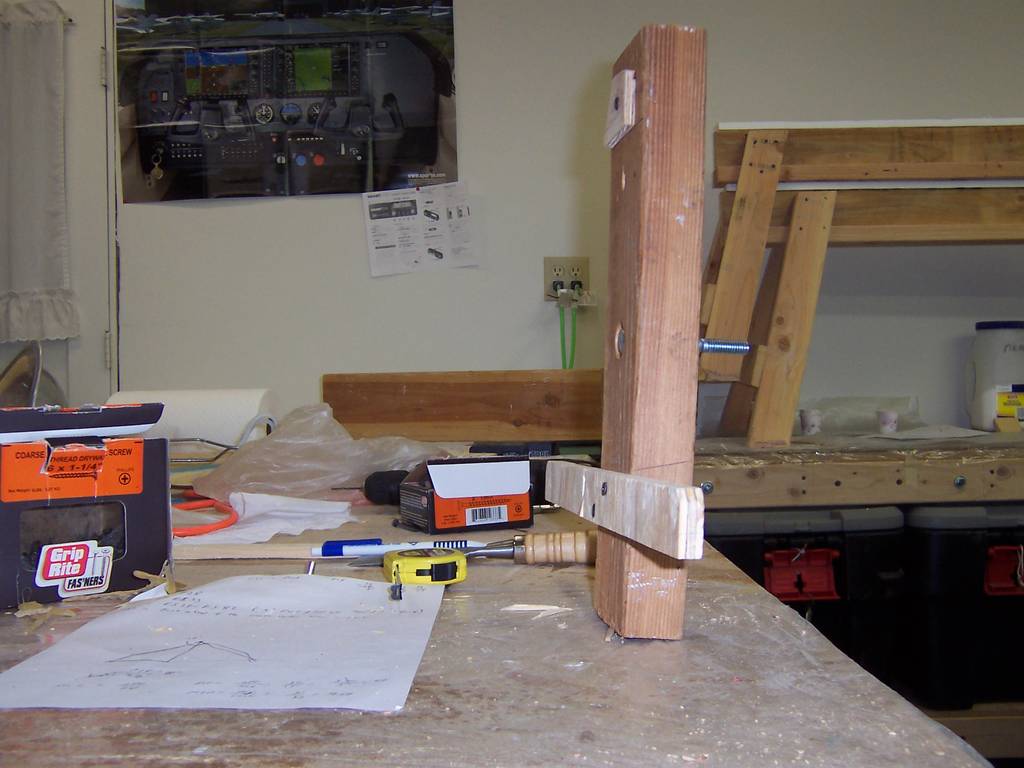
| Recognize these pieces of wood? They are from the forms used to build the sides! This is a front view of how they were built. The long piece of wood at the bottom is to give them some lateral stability. The small 2x4 block at the top is to get the frame far enough away from the fuselage so the "C" clamps will clear when rotated. | This is an angled shot. Both the front and rear frames were built the same. |

|
|
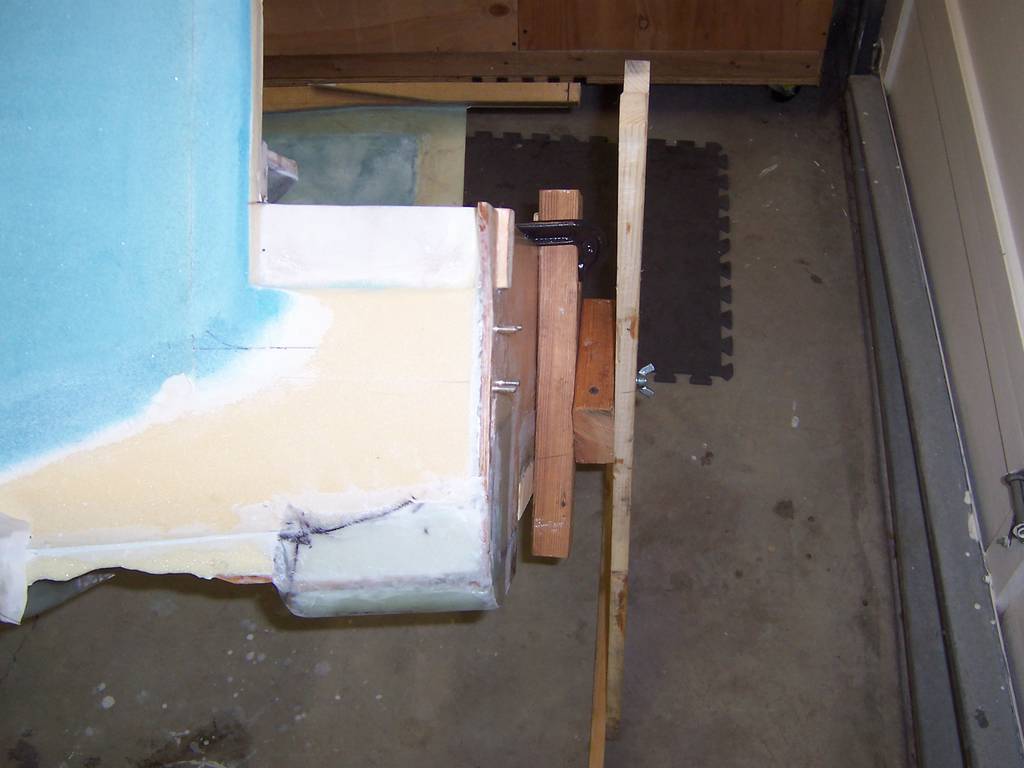
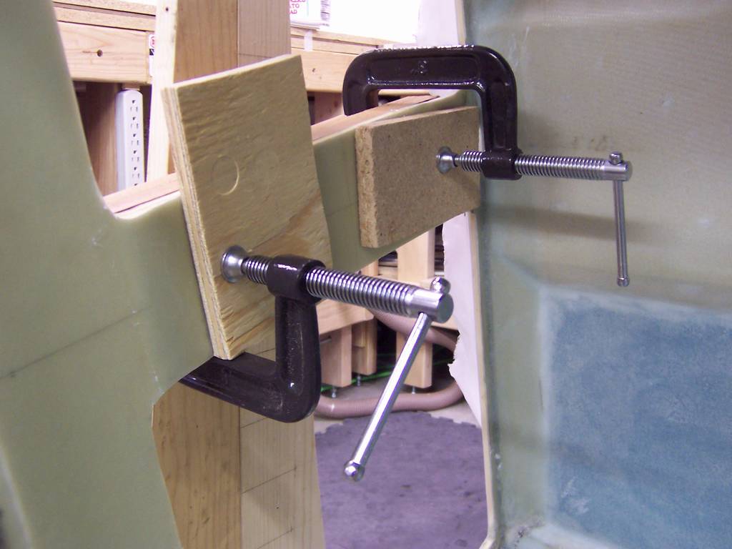
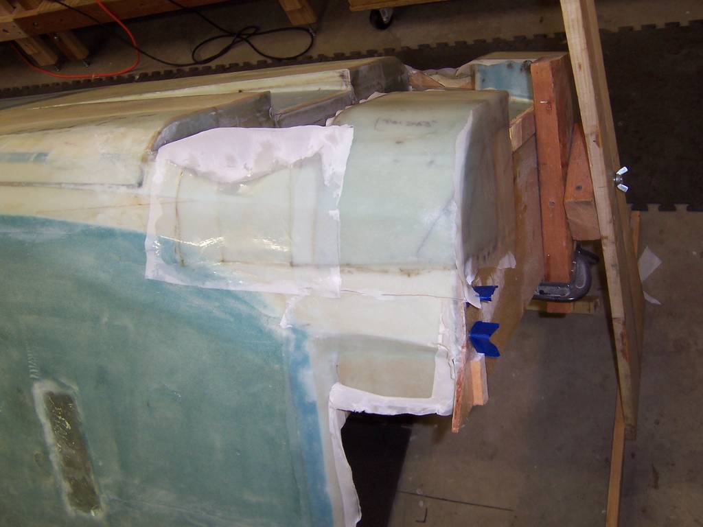
| The rear (firewall) support bracket. This was made from a piece of 2x6 I had laying around. The bottom horizonal piece of wood fits into the NACA scoop and prevents the the bracket from rotating. The small piece of plywood at the top is for the same purpose. The reason these are needed is the bracket is clamped only on the top. None of my clamps would fit on the bottom. | Side view of the aft support bracket. |
|
|
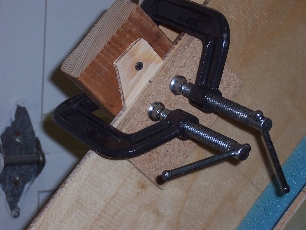
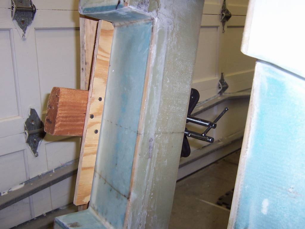
| View of the aft support with the bracket in place. | Close-up of the top of the aft support bracket. These two clamps are the only clamps used on the firewall. Note the small piece of plywood at the top of the bracket to keep the bracket from slipping. |
|
|
| Bottom of the aft support bracket. The horizontal piece of plywood keeps the bracket from sliding left and right. This was needed since there are not any clamps on the bottom of the firewall. All clamping is done at the top of the firewall. | Overall shot of the front of the rotisserie. |

|
|
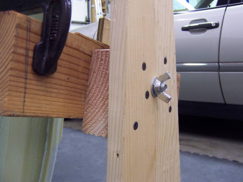
| Another overall shot of the rotisserie. | Close-up of the method of mounting the front support bracket to the rotisserie. |

|
|
| Side view of the front support mechanism. Note the need for the 2x4 to provide spacing for the clamps to clear the front support. The same is needed on the aft support. | View of the attachment of the front support bracket. This picture was taken from inside the fuselage. |
Fiberglassing the sides
The fiberglassing of the sides took two weekends. The first weekend Neil and I spent about 6-hours doing one side. The next weekend, Neil, Jeff and I spent about the same amount of time on the other side.
After the second side was completed, I installed the firewall reinforcement layups of three plys of UNI, 5-inches wide by 8 inches, 10 inches and 12 inches long. Over this was placed two layers of BID and a layer of peel ply.
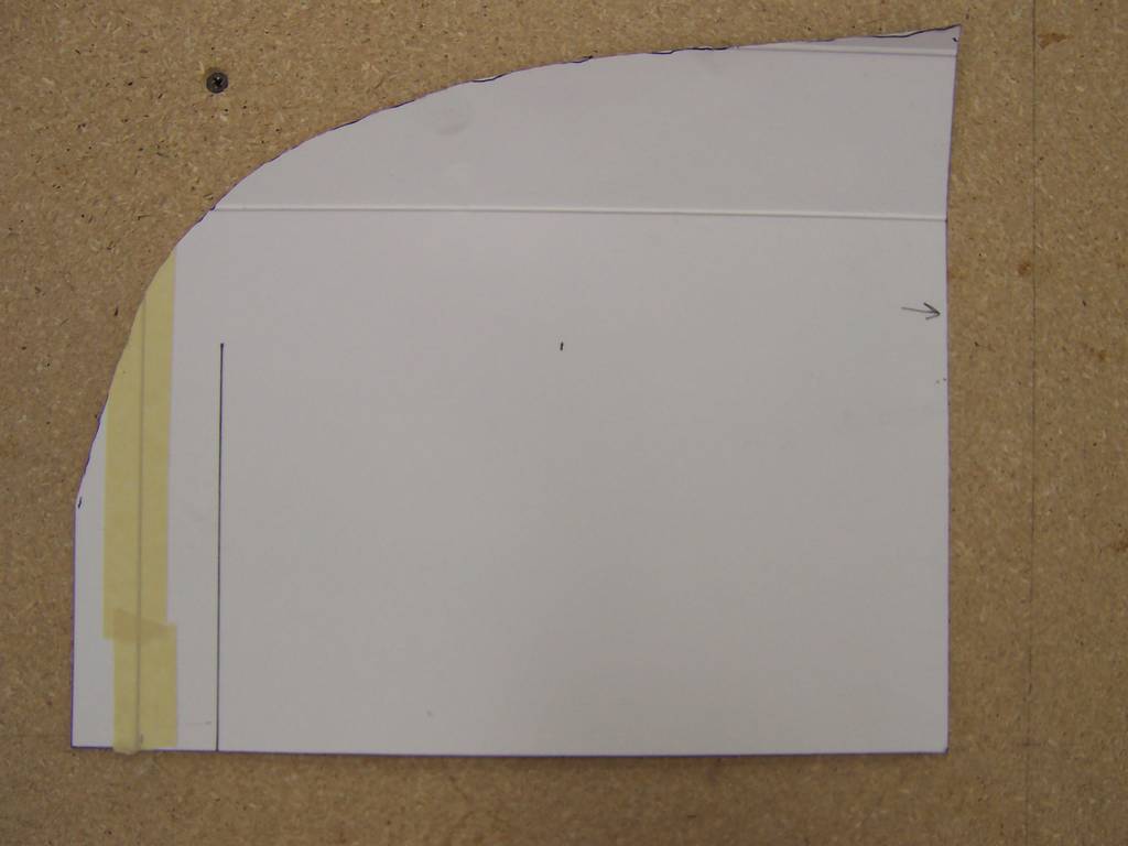
The UNI was not too hard to install, though I did have to take care to make sure there were no bubbles, especially when going around the edges. The BID, however, was a much bigger problem. Before starting the layup, I had tried molding some dry BID where the layup would be. I found I had to cut the BID with a curve so it would smoothly go around all of the edges. Even then it was a challenge to get it to lay flat. When the BID was wet with epoxy and it was two layers thick, it was really problematic to get it to lay flat. It required a lot of patience and cajolling to work all of the air bubbles out. I was really glad when I had finished and had put the peel ply on!
|
|
| I took a piece of BID and molded it onto the firewall. Then I cut it to shape. I then transferred the shape to this piece of paperboard. Using it, I traced the shape onto three other pieces of BID and cut it out. Even though the shape worked out well, it took a lot of patience to flatten the BID onto the firewall and to work out all of the bubbles. | The end result after the peel ply had been placed. |

|
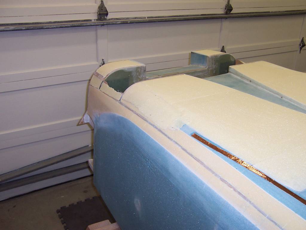
|
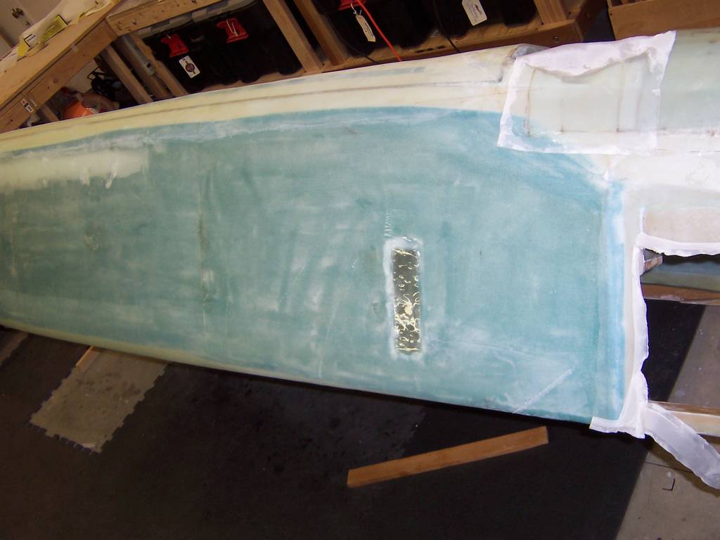
| The sides are finally fiberglassed! The large white area is alot of micro. This micro was used to fill the depression which resulted from using the Tim Lumpp bottom contouring tool. The tool worked GREAT, but it did leave a large unwanted depression on each side. | Another view of the fiberglassed sides. |