Page updated on: June 15, 2009
August 19, 2009
Chapter 10 - Building the Canard
Quick links within this page:
Step 1 - Trimming the Foam Blocks and Cutting the Cores
Step 2 - Making Lift Tabs, Inserts, Jigging Cores, Laying Up the Shear Web, and Installing Lift Tabs
Step 3 - Jigging and Bonding the Canard Sections Together
Step 4 - Spar Cap Layup
Step 5 - Applying the Bottom Skin
Step 6 - Installing Hard Foam Blocks for Elevator Hinges, the Upper Spar Cap and the Upper Skin
Chapter Overview
In this chapter the canard, using the R1145MS airfoil, will be constructed. The advantage of this airfoil is that it will not require a trim change when encountering rain. The canard is the most important and most critical airfoil in the airplane, so it must be constructed carefully.
Step 1 - Trimming the Foam Blocks and Cutting the Cores
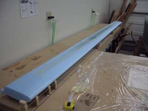
WoW!!! Finally, I'm making an airfoil! In this step, templates are created out of thin plywood. A hot wire is made and then, with the templates, is used to create the airfoil out of a block of foam.
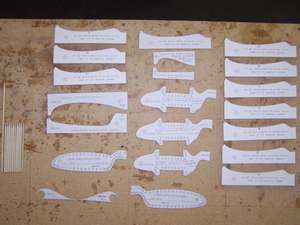
To make the templates, I scanned the images of them. Then printed them out on a laser printer. Naturally, the printed size was not the same as the originals. I had to adjust the scaling when printing them out. After about 5 or 6 attempts I had the proper scaling factors dialed in.
The printed shapes were then glued to the plywood and rough cut using a bandsaw. I then used sandpaper to remove enough of the plywood to away 1/2 of each line on the templates. I was very happy with the way they turned out.
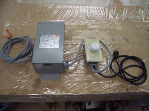
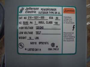
The hotwire tool was made using the method described in the education chapter. I did get lucky on the power suppy. Jeff had a transformer which was designed to increase a 220 Volt line to 240 Volts. I didn't know it, but this is a very common type of transformer. It is mostly used for industrial purposes. To give you an idea of what it is, I am posting a picture of the label of the transformer.
To control the voltage applied to the hot wire, Jeff purchased a $5 light dimmer from Home Depot. He wired this into the primary side (the side that is plugged into the wall). We found the ideal setting of the dimmer was just at about 75% of the maximum amount. I must say, it worked great!
Step 2 - Making Lift Tabs, Inserts, Jigging Cores, Laying Up the Shear Web, and Installing Lift Tabs
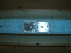
Like many other builders, the lift tabs I had purchased from Brock Engineering had smaller holes than specified in the plans. I just drilled them out so a 1/4" bolt would fit.
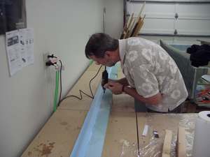
Other than drilling out the bolt holes, the installing of the lift tabs and the inserts went very smoothly. I used a router to make the holes for the inserts in the foam. This worked very well.
Step 3 - Jigging and Bonding the Canard Sections Together
The jigging of the canard is the assemble of the various pieces which need to be attached to it. This requires great precision so as to have a smooth and contiguous surface.
The jigging of the canard sections together went well. I think I would make the micro a bit thinner than I did. The reason is that it is hard to get it to squish out due to the dowels preventing the sliding of the foam pieces against each other.
Step 4 - Spar Cap Layup
This was a fun step. However, I believe the plans are a bit optimistic about doing both the spar cap layup and fiberglassing the bottom in one step. It took us about 5-hours to do the entire layup.
The spar tape was very difficult to wet-out. Neil, a cozy builder, helped me with this step and we both had trouble wetting out the spar tape. We did the best we could. This is the reason it took us so long to do this layup.
I kept careful records of how much spar tape I used. The total amount used for the bottom spar was 23 yards. The number of layers was 10.
Step 5 - Applying the Bottom Skin
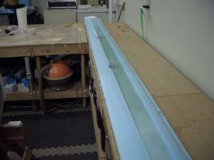
Applying the bottom skin was easy. It took about 4.5-hours. Jeff, a non-builder, helped. It does take two people as the strips of fiberglass are long and they need to be pulled tight before they are applied.
After reading another builder's write up on this step, I decided to cut 4 strips of BID. However, I only needed 3, as called out in the plans. The extra strip did not go to waste as I used it for one of the top layers.
Step 6 - Installing Hard Foam Blocks for Elevator Hinges, the Upper Spar Cap and the Upper Skin
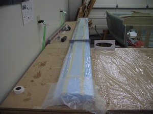
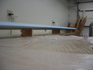
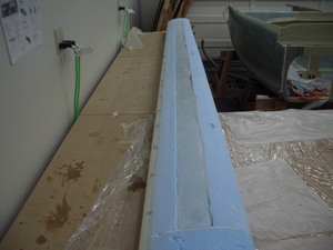
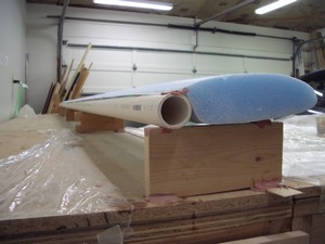
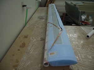
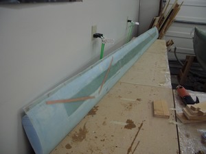
This was a long step with many sub-steps along the way. I used two pieces of PVC pipe to put along the trailing edge. I joined them with another piece of smaller PVC. It worked okay, not great, just okay.
One mistake I made was using very small dabs of Bondo to hold the PVC pipe on and to hold the canard to the pine boards and to hold the pine boards to the bench. To my disappointment, it all collapsed on me. The PVC pipe came off and the pine boards came off of both the bench and the canard. I then sanded the PVC pipe and this made a world of difference on how well it held the Bondo. I also used much larger blobs everywhere. This time, it was as solid as a rock! Even though the plans say to use a little, I would recommend using a little more! The canard is heavy and needs big blobs of Bondo to securely hold it in place.
Removing the peel ply from the trailing edge caused a bit of damage to the foam on the trailing edge. This was easily repaired using micro before the layup.
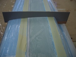
The top spar cap used 28 yards and took 12 layers of spar tape. This was another 5 hour layup. Again, we had trouble completely wetting out the tape. I'm beginning to wonder if there might something in the spar tape that is preventing it from completely wetting out. The un-wet areas are very small and are in strips about 1/2 inch long. There are not very many of them, but it was still frustrating trying to get it completely wet out.
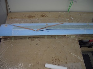
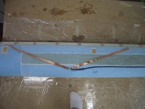
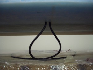
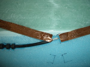
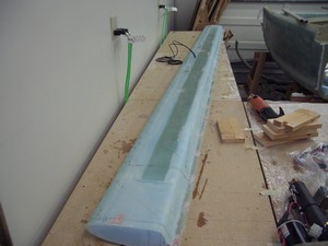
I had decided to put two 2-meter amateur radio antennas on the canard. One would be used for 2-meter voice and the other is for the 2-meter amateur radio Automatic Packet Reporting System "APRS" which is used by many for tracking purposes. The 2-meter radio sends your latitude and longitude to a website which then plots the position of your aircraft. The advantage of using ham radio is that it is a free service. However, you do need to have an amateur radio license to use the service.
My first choice would have been to put the antennas on the bottom surface. This is to have the slight "bump" in the fiberglass on the bottom which is less critical than on the top. However, this would have meant having to deal with the coax wire from the antennas when fiberglassing the top. I didn't want to mess with making holes in the wet fiberglass.
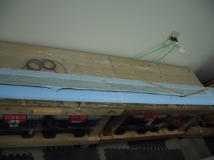
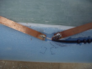
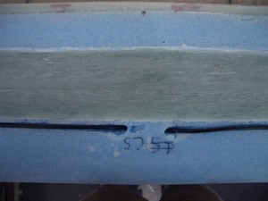
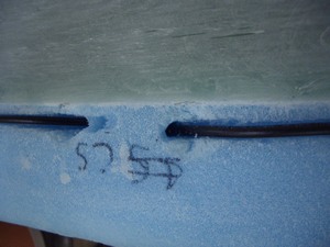
I then decided it would be easiest to put the antennas on the top. This was done after the bottom was fiberglassed. It was easy to route the coax to the center of the canard and then drill a hole through the bottom fiberglass. I then fed the coax through the hole. This made it easy to fiberglass the top of the canard.
I did not want to weaken the top spar, so I placed the antennas over it, rather than routing out a trough for them to lay in. I did route a trough for the coax and the torroids so they would be below the surface of the foam.
During the layup, I did have some difficulty with the antennas laying flat against the surface of the foam. Since I had not attached them to foam, they were just lying on top of it. If I had it to do again, I would have epoxied the antennas down using 5-minute epoxy. This would have made it easier when laying the fiberglass.
Yea! It's time to move on to chapter 11!
