Page updated on: August 19, 2009
December 7, 2009
Chapter 11 - Building the Elevators
Quick links within this page:
Step 1 - Cutting foam cores and bonding to the torque tubes
Step 2 - Installation of the bottom skin
Step 3 - Installation of the top skin
Step 4 - Installing the NC-6 inserts and the NC-3 hinges in the canard
Step 5 - Checking elevator travel and installing tip fairings
Step 6 - Installing the pitch trim belcrank and the elevator mass balance weights
Chapter Overview
In this chapter, I will manufacture and mount the elevators on the canard. The elevators are the primary pitch control surfaces. They are a simple, hinged, slotted flap attached to the canard. They move up or down together as the control stick is moved fore and aft.
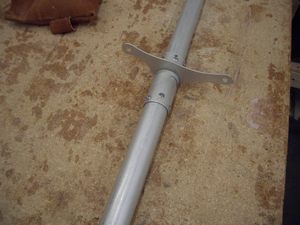
The elevators are cut out of styrofoam using a hot wire cutter. Then they are bonded to an aluminum tube and fiberglassed. Hinge brackets will be installed as well as balance weights. Finally, the elevators will be attached to the canard.
The critical requirements in this chapter are:
- The elevator contour must be exact to insure pitch stability
- The elevator weight must be as light as possible and balanced to avoid flutter
Step 1 - Cutting foam cores and bonding to the torque tubes
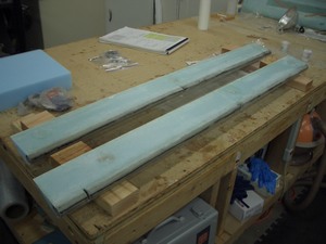
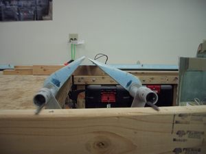
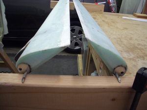
Jeff and I hot wired the elevator cores in one evening. I believe I had the wire too hot as the thin leading edge that goes around the aluminum tube curled a little bit.
Jeff and I discovered it was best to cut from the trailing edge to the leading edge. This is opposite from the numbers on the templates. By the time the hot wire got to the leading edge, it had cooled down enough, on the second core, that the leading edge did not curl.
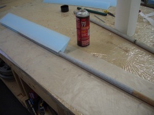
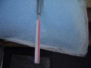
The cut out for the aluminum tube was a little bit small. I used some 3M super 77 spray adhesive to hold a couple of sheets of #60 grit sandpaper to a broom handle. Two passes of this through the holes was enough for the aluminum tube to fit.
Step 2 - Installation of the bottom skin
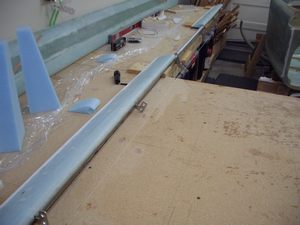
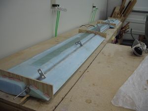
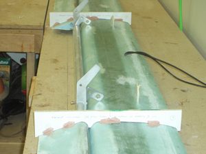
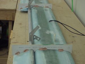
Installing the bottom skin was really easy. Once it cured, it looked great.
I did have two hiccups when fiberglassing the top of the elevators. First, I rounded the foam on the trailing edge a little too much. This meant I had to have more micro than I think is normal. Unfortunately, the placing of the micro was at the end of the layup and I was tired, even though it was only a two hour layup. I didn't do a very good job.
The next day when I checked the contour with the template, the trailing edge didn't match up very well. I then added more micro and really worked it well till it was just about perfect. The result looks really good. However, there was one spot that needed a bit more micro, so when I added the end pieces, I put a little more micro in that one spot. It looks perfect now.
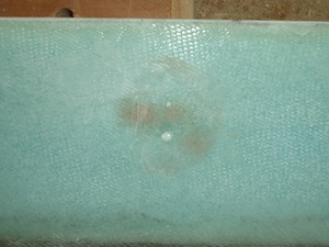
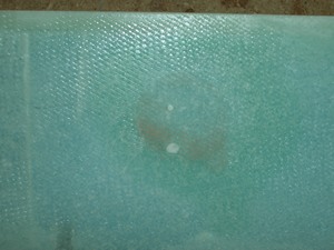
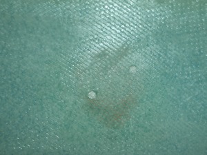
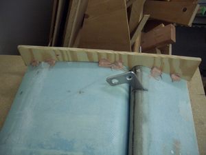
The second problem I had was using too much bondo. I was tired of using just a little bit of bondo, as the plans are always saying. I used sparing amounts of bondo on the canard it completely collapsed just before I was going to fiberglass it. The pipe along the trailing edge even popped off! I didn't want to take that chance with the elevators. So I used a big glob, about a half-inch in diameter in three places on the bottom of each elevator. This spread out to a circle about 1.5 inches in diameter when I push the elevators onto the bench. Boy, it held really well!
When it was time to remove the elevators from the bench, I carefully used a chisel to get under the elevator to lift it off the table. I heard some omnimous sounds of cracking foam as I forced the elevator off the table. I was as careful as I could be, but damaged it anyway. Upon inspection, the damage was a 2 to 3 inch area around each bondo blob that was soft when pushed with a finger. This was caused when the fiberglass was torn away from the foam.
Yesterday, I went to Walgreens and they gave me a 5 ml syringe, without a needle, which they give to parents with small children. I drilled two holes at each bondo blob at the edges of the softness. I injected some epoxy and watch it fill the entire area beneath the bondo blob and come squirting out the second hole. It was really cool to see it actually work! After curing, these spots are now hard as rocks. I think the problem is solved at the expense of a bit of extra weight on each elevator.
Step 3 - Installation of the top skin
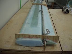
Fiberglassing the top of the elevators was easy. No problems were encountered.
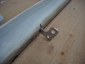
Step 4 - Installing the NC-6 inserts and the NC-3 hinges in the canard
Step 5 - Checking elevator travel and installing tip fairings
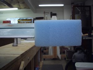
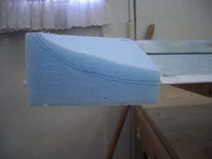
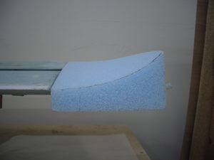
In this step, the amount of up and down elevator travel is verified as being within the acceptable range. Also, the tip farings are made from a block of foam.
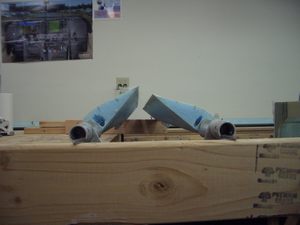
I was quite pleased with the elevator travel I had. It meets the specifications of +30° and -15°.
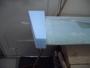
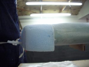
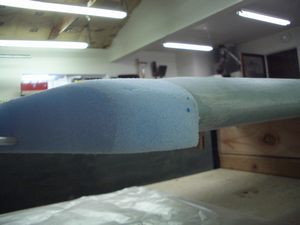
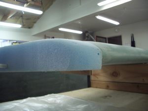
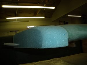
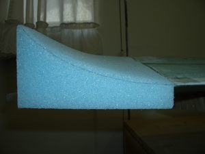
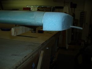
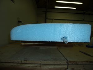
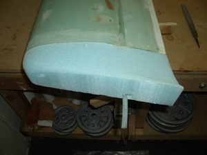
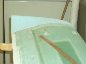
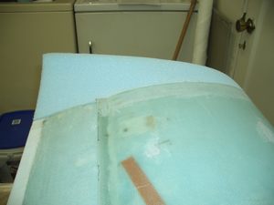
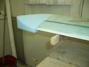
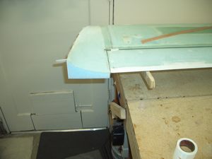
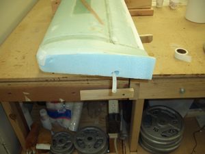
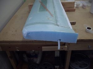
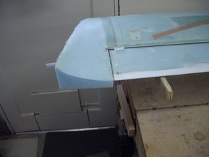
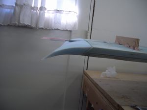
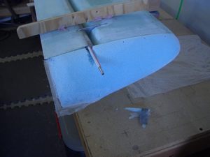
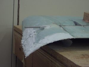
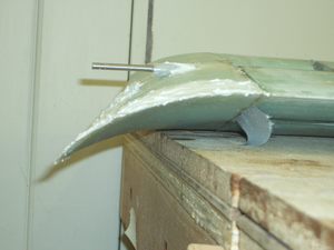
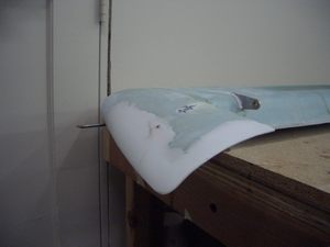
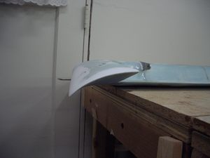
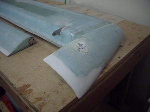
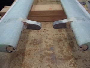
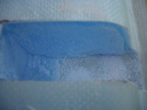
I was a bit aprehensive about making the tip fairings. The right side of my brain does not get much practice and I was worried I would not be able to get a pleasing curve. Fortunately, it turned out to be pretty easy, however, on the right side I sanded a little too much. This was easily fixed by piling on micro and sanding it down to shape.
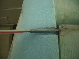
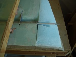
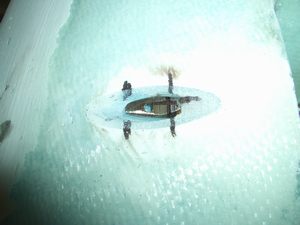
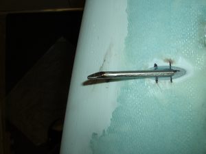
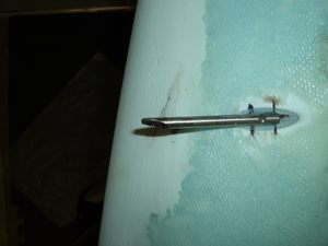
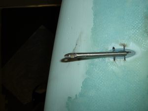
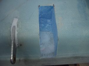
Originally, I was planning on using some tubing to go over the elevator hinge, however, the walls of the tubing were too thick. Notice how the top of the hole for the elevator hinge is missing. There is not much clearance between the elevator hinge and the top of the tip after shaping. I then changed to using a McDonald's soda straw. This straw was left over from the tubing used for the brake lines on the landing gear.
Step 6 - Installing the pitch trim belcrank and the elevator mass balance weights
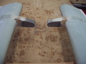
This step went very easily. The mass balance weights were installed and they balanced as expected.
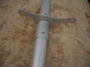
Installing the pitch trim belcrank was also very simple. No problems were encountered.
On to chapter 12!
