Page updated on: November 30, 2007
Chapter 6 - Fuselage Assembly
Quick links within this page:
Step 1 - Assembly of the fuselage sides
Step 2 - Center keel and seatback brace
Step 3 - Contouring and installing the fuselage bottom
Chapter Overview
In this chapter, the plane becomes three dimensional as the bulkheads are attached to the fuselage sides.
Step 1 - Assembly of the fuselage sides
It took me two weeks to start on chapter 6. I had read several web pages about chapter 6 and the builders had mentioned how the bulkheads perfectly fit onto the sides. Well, during a quickie trial fit, with the fuselage sides still on the forms from chapter 5, my bulkheads did not fit. Arrrrgh! There were 1/4 to 1/2 inch gaps between the bulkheads and the sides. I was really bummed out as I *thought* I had been very careful and accurate while making the bulkheads.
It took me about two weeks to recover. During that time I was sick and I strained my back when moving the sides and the forms at the sametime from the table to the floor. At the end of the two weeks, I decided to bite the bullet and start tweaking the sides by hacking and sanding them till they fit.
So I dove in with gusto and my Fein tool in one hand and a big saw in the other! Those bulkheads were going to fit, even if I had to trim them so much the cockpit would be much narrower! I started with evaluating how the bulkheads contacted the spacers on the upper and lower edges of the fuselage sides. I put the HSS cutting blade on the Fein tool and whacked off a bit of the bulkheads where they contact the spacers on the fuselage side. The angle on the bulkheads did not match the spacer. Surprisingly, it didn't take much, I only cut off about a quarter inch at one corner. Then another quarter inch at another corner and so on. Low and behold, I got a perfect fit!!! That's was all? It was that easy? It took me all of about an hour to get an acceptable fit AND the fuselage is still at the plans width!! WoW!!! What a surprise.
Next, I put the sanding disk on the Fein and made a bunch of minor tweaks to get an even better fit. The only area I could not get a fit was on the seatback around the upper and lower longerons. There was still a considerable gap there, which I filled with flox.
The next task is to assemble the bulkheads to the sides. The plans recommend doing this on the floor using a long wide plank. This plank must be made perfectly level. Then the sides are put on it. After reading the step multiple times, it looked like it was going to be difficult to keep everything the perfect distance from each other, perfectly level, perfectly square, perfectly horizontal and perfectly vertical. Notice the use of the word "perfect". The plans said everything needed to be "perfect" so the plane will fly straight. Hmmmm, after my experience with how "perfect" I had made the bulkheads, I was a bit concerned. Then reading various web sites and chatting with other builders, I saw Wayne Hicks had come up with a better way of jigging the fuselage.
Wayne's method was to jig it upside down on the work bench. The reasoning was it would be easier to keep the longerons level if they were on a level table, rather than being balanced across a narrow board. This made since. However, there was one problem, how do you "squeeze" the sides together while the flox is curing? The plans recommend putting straps around the fuselage while it is curing. Wayne had used screws to hold the sides to each bulkhead, but for no particular reason, I felt uncomfortable using them in the foam. I think it is because I don't trust the screws to hold well in the foam and they might strip out. So, I continued searching for a way to jig the fuselage.
As I was reading various pages about jigging the fuselage, I noticed Tim Andres' had come up with a very simple solution. He had used Wayne Hick's idea of jigging the fuselage upside down on the bench, but had put a couple of 2x4 studs between the bench and the fuselage sides. This gave him room under the plane to put straps. Walla, problem solved.
Now that I had a plan, it was time to put it into action. Since the instrument panel will extend below the top of the table, I had to move my table apart by about 18 inches. This was easy as my bench is made up of 6 smaller benches, all bolted together. So a friend and I unbolted the middle benches and slid them apart. However, since my garage floor slopes, I had to relevel the bench section that I moved. This took about an hour, so it wasn't a big deal.
Next, the temporary firewall was screwed to the end of the bench and the sides inserted into it. The bulkheads are then placed in postion to check for fit. Hmmmm, they didn't fit as well as they did with the sides laying on the table in their forms. What went wrong? Well, I had forgotten the sides had a large curve in them. When I had adjusted the bulkheads to fit, I had used the wrong angle between the sides and the bulkheads. OK, no big deal, I'll just adjust them slightly using the Fein sander. Again, the problem was in the area of the spacers. Fortunately, with all of the tweaking I have done, the straight portion of the sides of bulkheads, where they contact the fuselage sides, have not needed sanding, they were straight. So, the width of the bulkheads has remained the same, only the compound angles for matching the spacers have been changed.
|

|
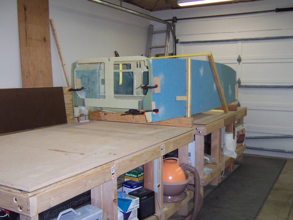
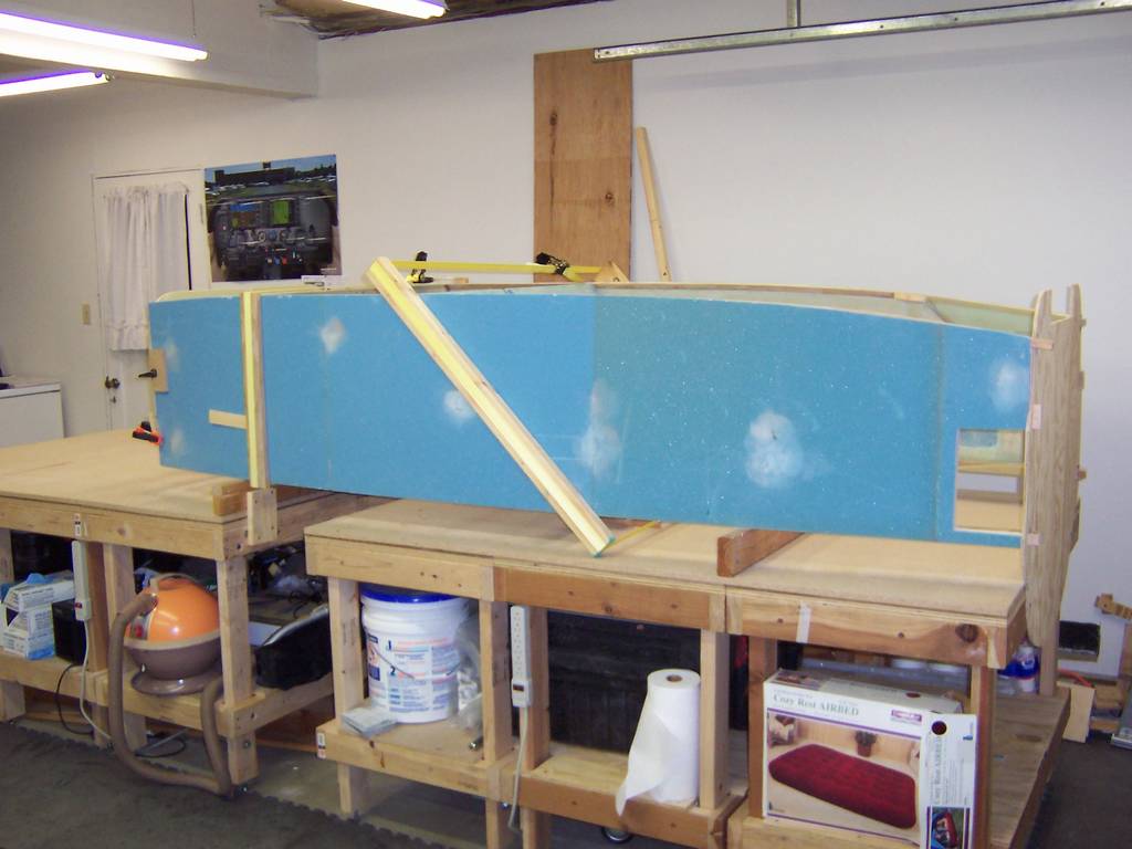
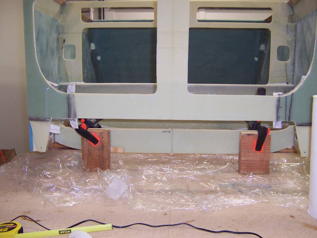
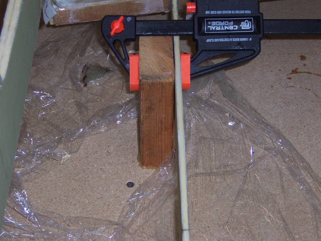
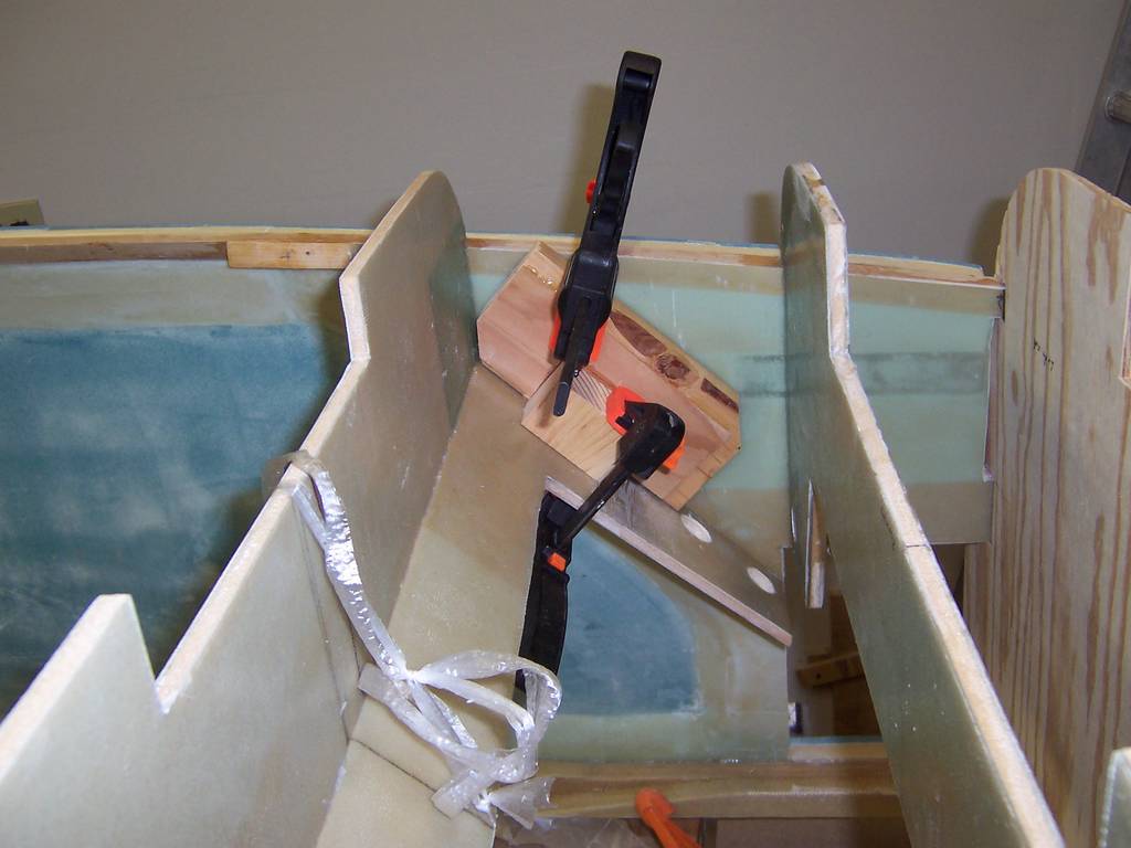
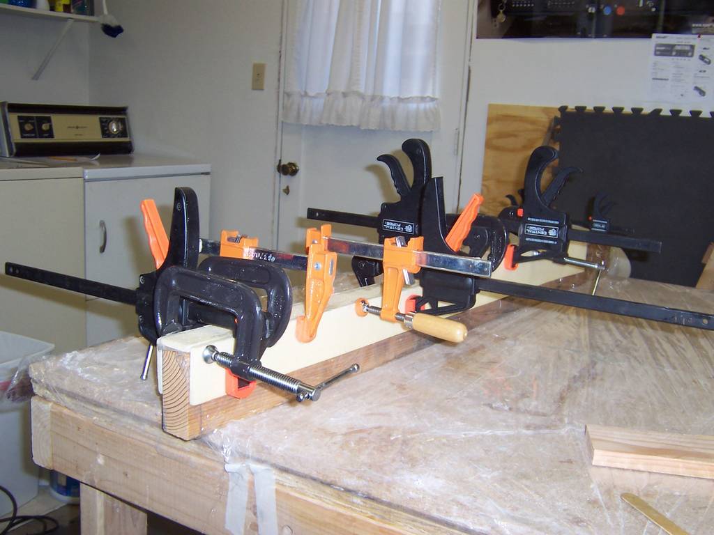
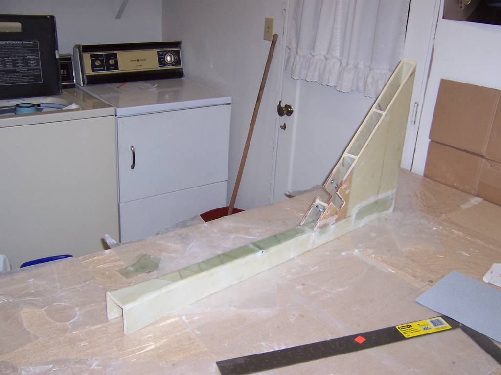
| Overall view of fuselage after floxing bulkheads to the sides. Note the fuselage is upside-down on the table. | Close up of the forward clamp used to hold the bulkhead against end of the fuselage and the clamp needed to hold the side of the fuselage against the side of the bulkhead |

|

|
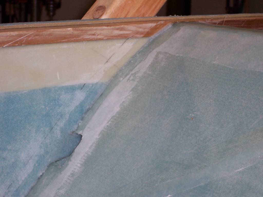
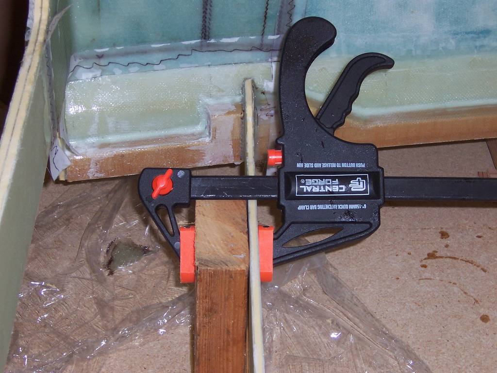
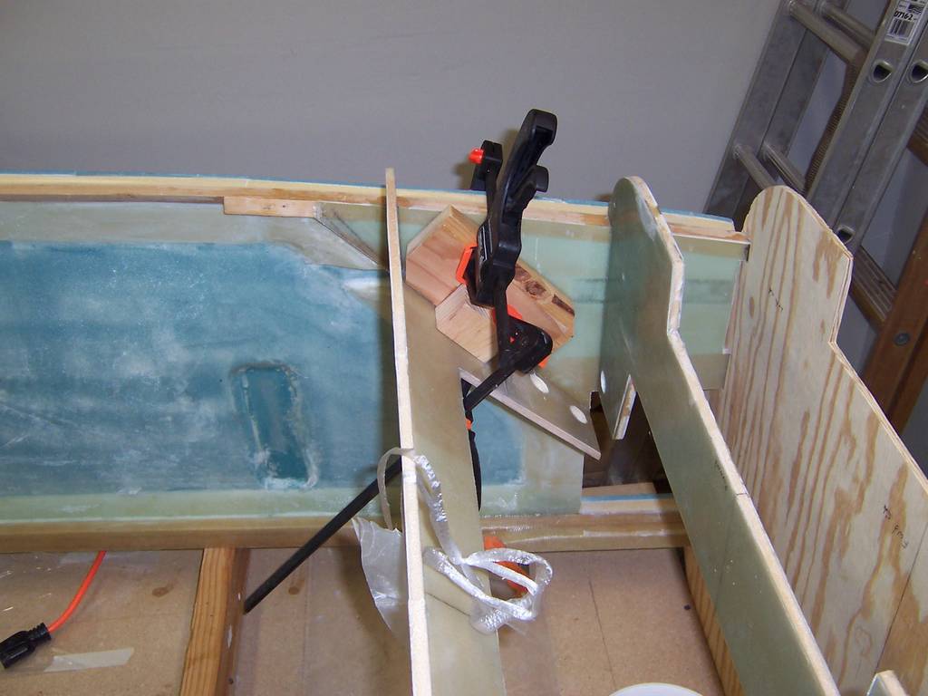
| The clamp on the side of the fuselage used to hold the bulkhead against the end of the fuselage | Fuselage side after floxing bulkheads to the sides |
|
|
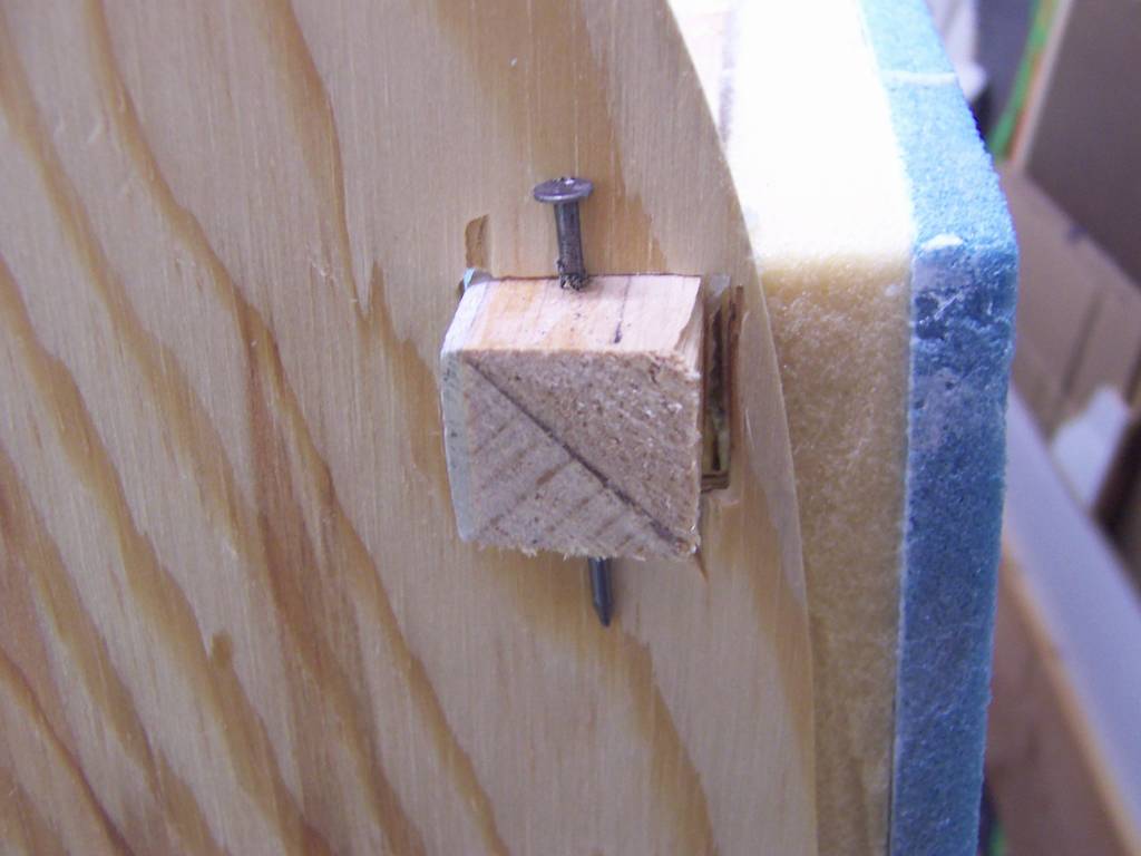
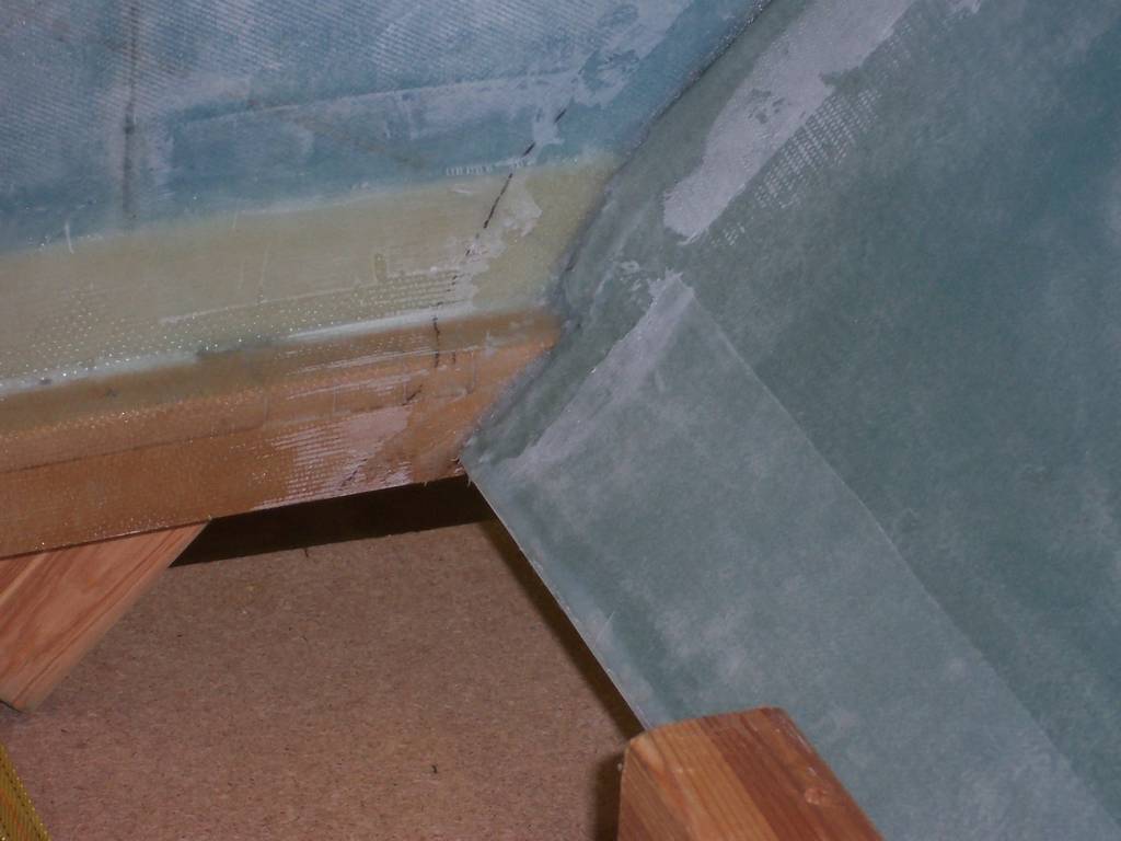
| Aft portion of fuselage side | Nail used to hold the firewall against the aft end of the fuselage |
|
|
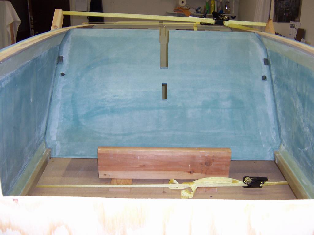
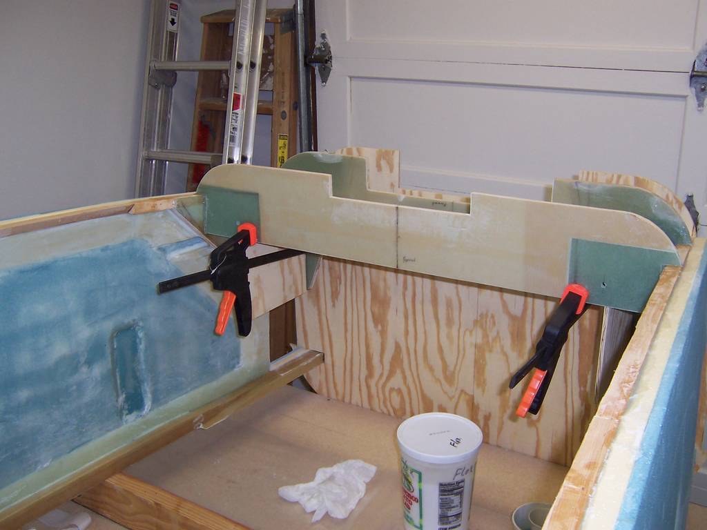
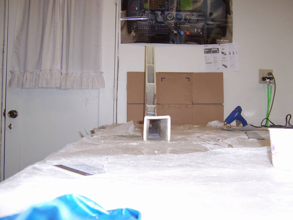
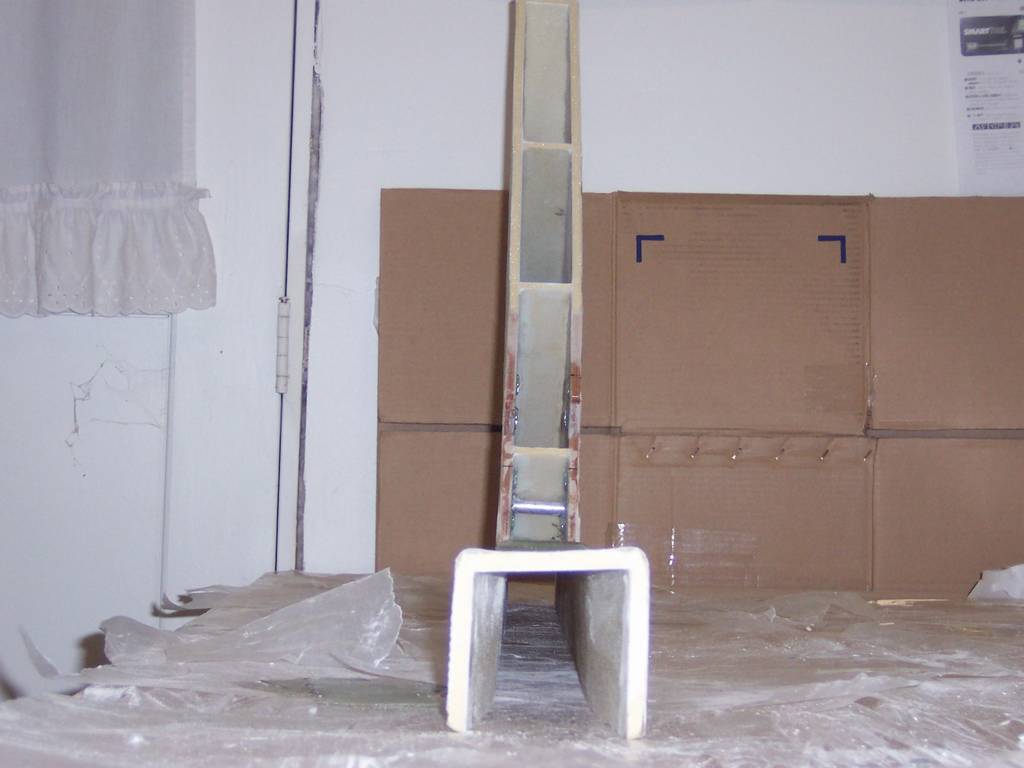
| The back side of the front seat back. Note the fuselage is upside-down on the table | Close up of the aft 2x4 stud used to support the fuselage. Since the fuselage is upside-down, the upper longerons are contacting the 2x4. |
|

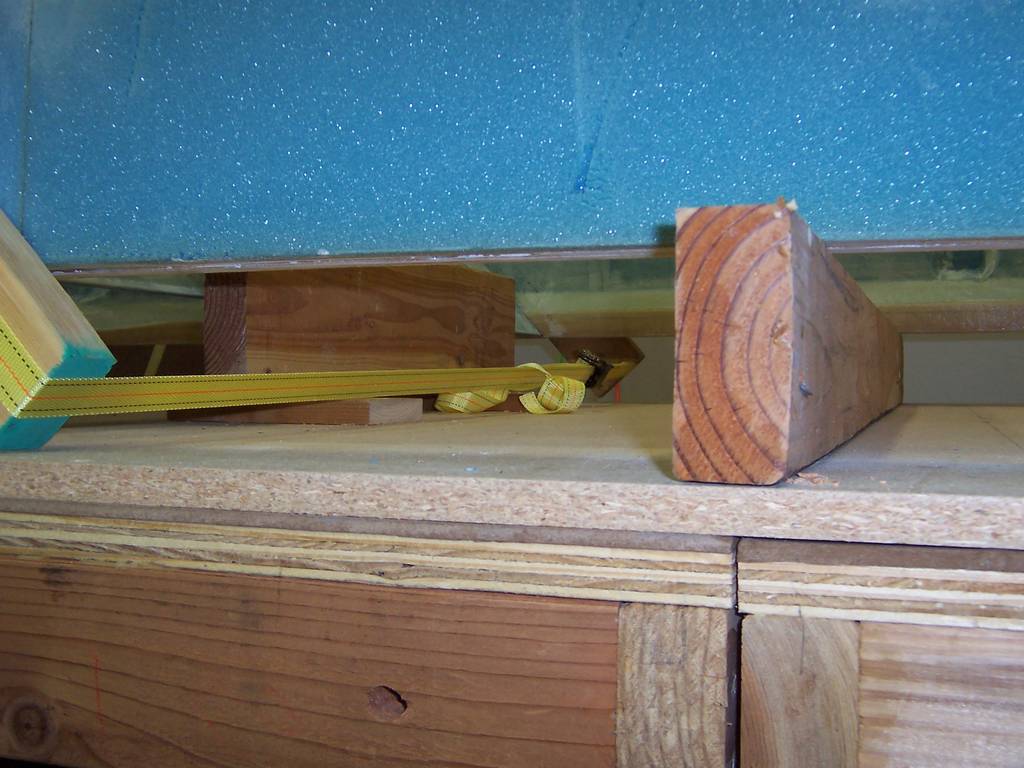
|
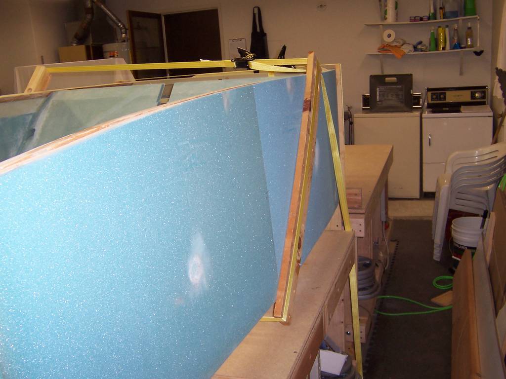
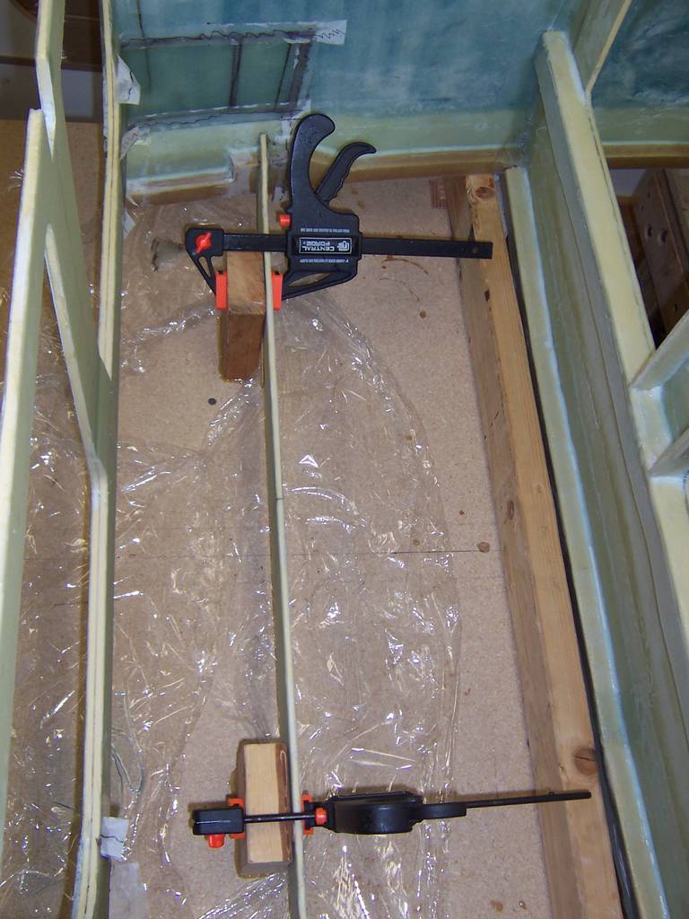
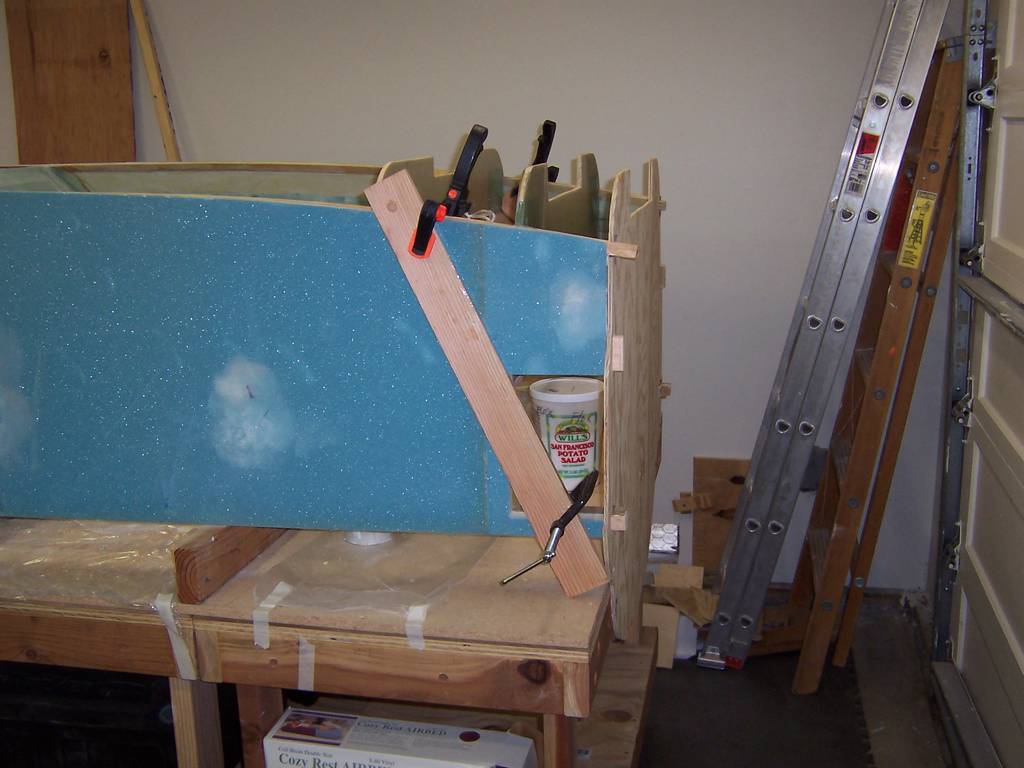
| Side of the fuselage after floxing the bulkheads in place | The wood on the side of the fuselage has straps on it connecting it to a piece of wood on the other side. The straps have been tightened so the wood is applying pressure on the sides to hold it against the bulkheads. |

|
|
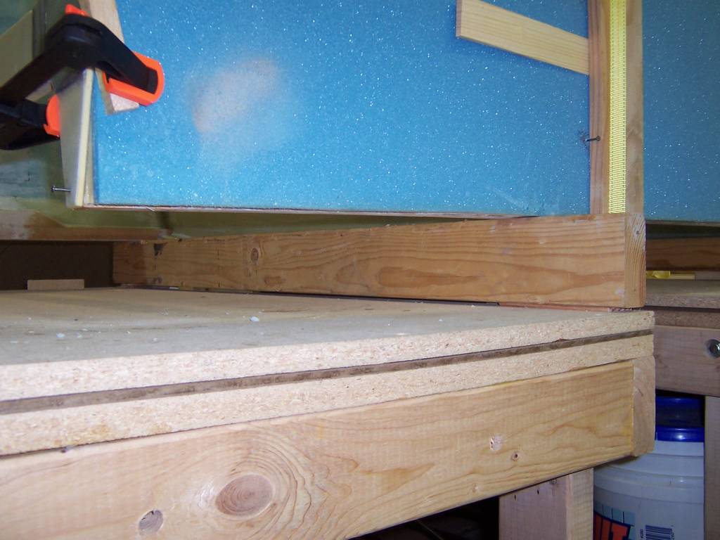
| The front 2x4 was held to the table with a plate attached to the edge of the table. Also, you can see how the instrument panel extends below the top of the table. | The boards holding the sides together needed a couple of shims to make a good fit between the sides and the bulkheads. |
|
|
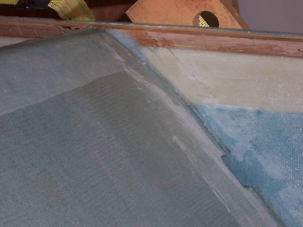
| Alignment of the bottom LHS of the front seat back. | Alignment of the bottom RHS of the front seat back. |
|

|
| Alignment of the top portion of the back of the front seatback on the RHS to the sides. | Alignment of the top portion of the front of the front seatback on the RHS to the sides. |

|
|
| Alignment of the top portion of the front of the front seatback on the LHS to the sides. | F22 being clamped in place while the flox cures. This is another advantage to assembling the fuselage upside-down as blocks can be glued to the top of the table to hold F22 in place. |
|
|
| F22 being held in place during cure. | Another picture of F22 being held in place. |
|
|
| Another picture of F22 being held in place. | Landing gear bulkheads being held in place during cure. |
|
|
| Landing gear bulkheads being held in place during cure. | Landing gear bulkheads being held in place during cure. |

|
|
| Landing gear bulkheads being held in place during cure. | Landing gear bulkheads being held in place during cure. |
|
|
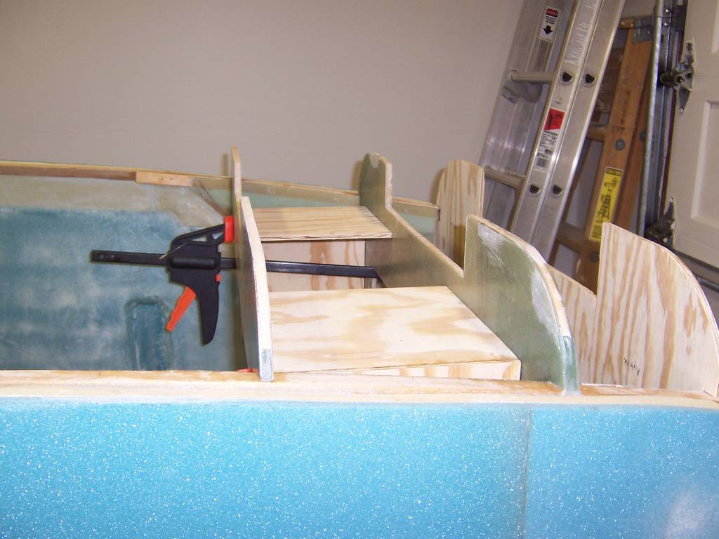
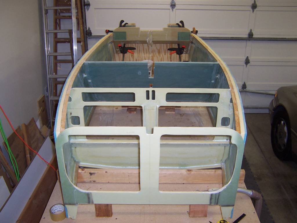
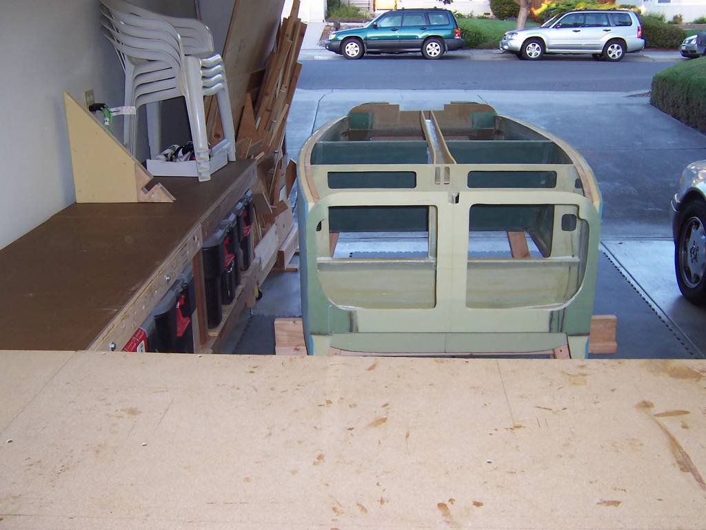
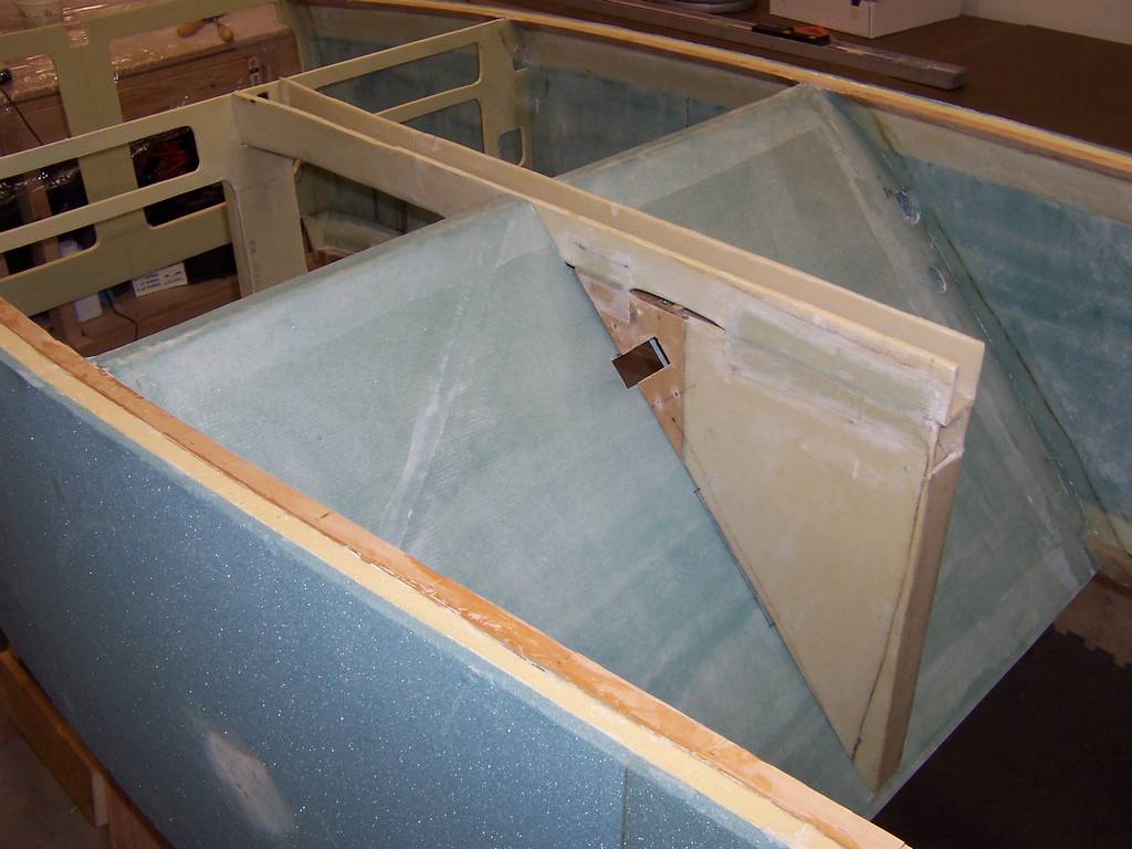
| Landing gear bulkheads being held in place during cure. | YEA!!! I am finally to the stage where it is 3-dimensional! It really feels good to be looking at the plane as more than a collection of flat pieces! |
Step 2 - Center keel and seatback brace
The center keel is also the heat duct. The original use was to direct heat from the engine to the front of the cockpit. Since I plan to have a water cooled rotary engine, my plan is to run hot water pipes to a heat exchanger in the nose. This will then be used to heat the cockpit.
The seatback brace is to support the front seatback. It also has a map pocket in it and the fuel valve. Again, I needed to make a change. The engine is fuel injected, so it needs a return line from the engine to the fuel tank. This means using a 6-port fuel valve where there are both feed and return ports for each fuel tank. The fuel valve we selected is one sold by Bulent Aliev. This valve needed to have a different bracket to hold it in place. It also meant the fuel lines for the engine need to exit at the bottom of the seat brace rather than from the sides.
At this point in the construction, the large table is not needed for many chapters. I don't think it ever needs to be 4-foot wide again. When I designed the factory, I wanted the table to constructed so it could be disassemble into smaller sections. I chose a unit that is 2-foot by 4-foot. I made 6-tables this size and bolted them together. Now I can take them apart and have the main section of the table 4-foot wide and 8 feet long. The other two tables have been put against a wall. This section is 2-foot wide by 8-feet long, however, since it butts against the other section makes it another 4-feet longer.

|

|
| Holding the foam pieces for the heat duct together while the 5-minute epoxy cures. | End view of the heat duct. |
|

|
| The foam for the heat duct was formed around a 2 x 4 piece of wood so the sides would be perpendicular to the top. Also, the 2 x 4 was the same width as the inside of the heat duct. | The plywood bracket for the fuel valve. |
|

|
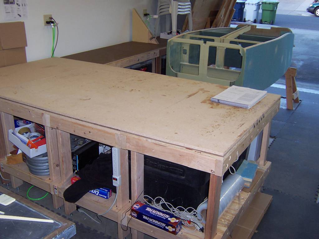
| Plywood bracket for the fuel valve. | An overall view of the rearranged factory and the plane sitting on the saw horses. |
|
|
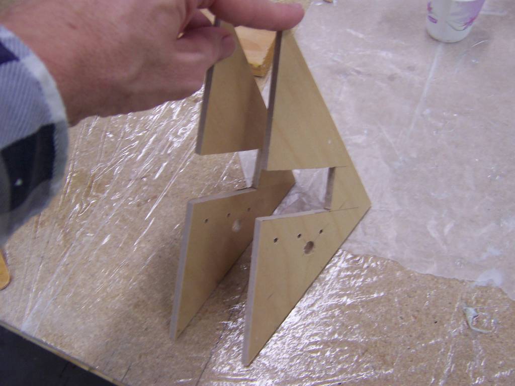
| The factory has been rearranged. The table is arranged in an "L" configuration with 3 of the tables against the wall and 3 of the tables extending toward the center of the factory. | Another view of the rearranged factory. The triangular piece on the left side is is the seat back brace with the fuel bracket attached. This is before the seat back brace is mounted to the heat duct. |
|
|
| Assembled heat duct and seat back brace. | End view of the assembled seat back brace and heat duct. |
|
|
| Assembled seat back brace and heat duct. | The heat duct and seat back brace are in place for a trial fitting. Looks good! |
Step 3 - Contouring and installing the fuselage bottom
The making of the fuselage bottom was fairly easy and quick. So quick, I didn't get a chance to take any pictures.
This step starts out by placing foam on the bottom of the plane. A frame is then built on top of the foam to maintain the curvature of the bottom. Once the frame has been glued to the bottom, the bottom, with the frame, is transferred to the work bench.
Additional foam is added to the edges and the middle part of of the bottom which will become the interior. This will give the bottom shape and support.
Once the foam has been added, then two layers of fiberglass are added to the entire inside surface of the bottom. This is a two man job and Neil, who is building a Cozy Berkeley, stopped by to help out. It took us about 5-hours to complete the task.
After the fiberglass had cured, I transferred it to the bottom of the plane. I then crawled underneath the plane and put strips of fiberglass on all of the interior edges where the bottom meets the fuselage sides, heat duct, forward bulkhead, Instrument panel, front seat and the landing gear bulkhead. This was very tedious as I was applying the fiberglass over my head (remember the plane is up-side-down). I was really tired by the time I finished.
I have a funny story to tell with regards to applying the fiberglass to the bottom while working under the plane. At some point, I had wet fiberglass behind and above me. I managed to touch my hair to the wet fiberglass, multiple times, without realizing it. A few hours later I was watching TV (I was really tired), and touched my hair. Ohhhh NO! The epoxy in my hair had cured. I tried everything to get it out, but nothing worked. Oh well, I went to bed with my hair in many clumps. It really looked funny. The next morning, I figured I would have to go to the barber to get it all cut out. As usual, I took a shower and washed my hair. After toweling off, I decided to try one more time to get the epoxy out of my hair. Whew! I got lucky, I was able to "slide" the epoxy out of my hair, though it took about 45-minutes to get it all out. I guess the shampoo and water had lubricated it enough that I could pull it off my hair without pulling my hair out. I was sure glad I didn't have to get a unique and funny looking haircut!
Yea!!! Chapter 6 is done!!! Now, on to chapter 7.