Page updated on: February 27, 2008
March 5, 2008
March 9, 2008
April 6, 2008
September 14, 2008
December 1, 2008
December 15, 2012
Chapter 9 - Main Landing Gear and Landing Brake
Quick links within this page:
Step 1 - Landing Gear Bulkhead Reinforcements
Step 2 - Preparing the Landing Gear Strut for Installation
Step 3 - Making the Attach Tabs and Installing the Landing Gear Strut
Spot Face Cutting Tool
Step 4 - Making the Landing Gear Cover
Step 5 - Installing Axles, Brakes, and Brakelines
Step 6 - Constructing the Landing Brake
Chapter 9 Summary
Chapter Overview
In this chapter I will install the main landing gear and landing brake. I will start by adding reinforcing layups to the landing gear bulkheads and firewall, trim the main gear strut to length, sand it dull, and then layup 8 plies of UND at 35 degrees over the entire strut for torsional stiffness. I will install a conduit for the brake lines and feather the trailing edge for minimum drag. I will jig the strut into position on the fuselage, make the attachment glass tab layups, and assemble the gear on the fuselage. With the strut installed, the axles are mounted. The landing gear cover is also built at this time.
The main gear strut was especially designed for the Cozy. It is a one piece, 30 lb., airfoil shaped, S-glass molded part, available from Featherlite.
Finally, the landing brake will be cut out from the bottom of the fuselage and installed. Once installed, it will then be fiberglassed. I also plan to install the electric landing brake actuator.
Whew! there is a lot to be done in this chapter. I guess I better get started!
Step 1 - Landing Gear Bulkhead Reinforcements
This was a step I was not looking forward to. It is a series of difficult layups in hard to reach places. The first layup was on the forward landing gear bulkhead to the floor of the fuselage. The second layup was between the two landing gear bulkheads. The third layup was between the aft landing gear bulkhead an the firewall.
Before starting the layup, the "bump" caused by the lower longeron doubler needs to sanded down so the fiberglass will smoothly transition from the longeron to the floor of the fuselage. The "bump" is actually more than a bump. It was a bit confusing to me as to what was meant. Therefore, I have taken several photos showing the before and after shots of the "bump".

View of the "bump".
Close-up of the "bump".
The "bump" has been sanded to shape.
A smooth transition of the longeron to the floor of the fuselage
A side view of the smooth transition of the "bump".
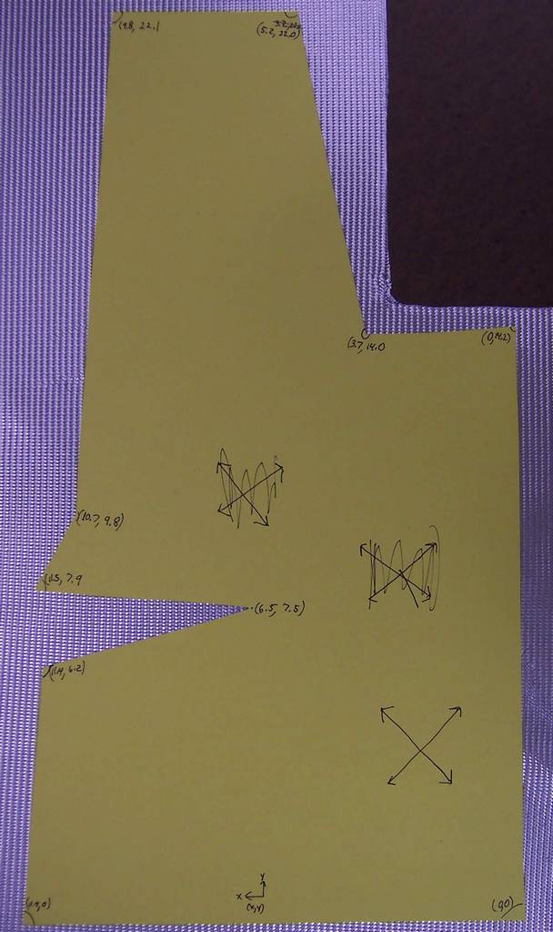
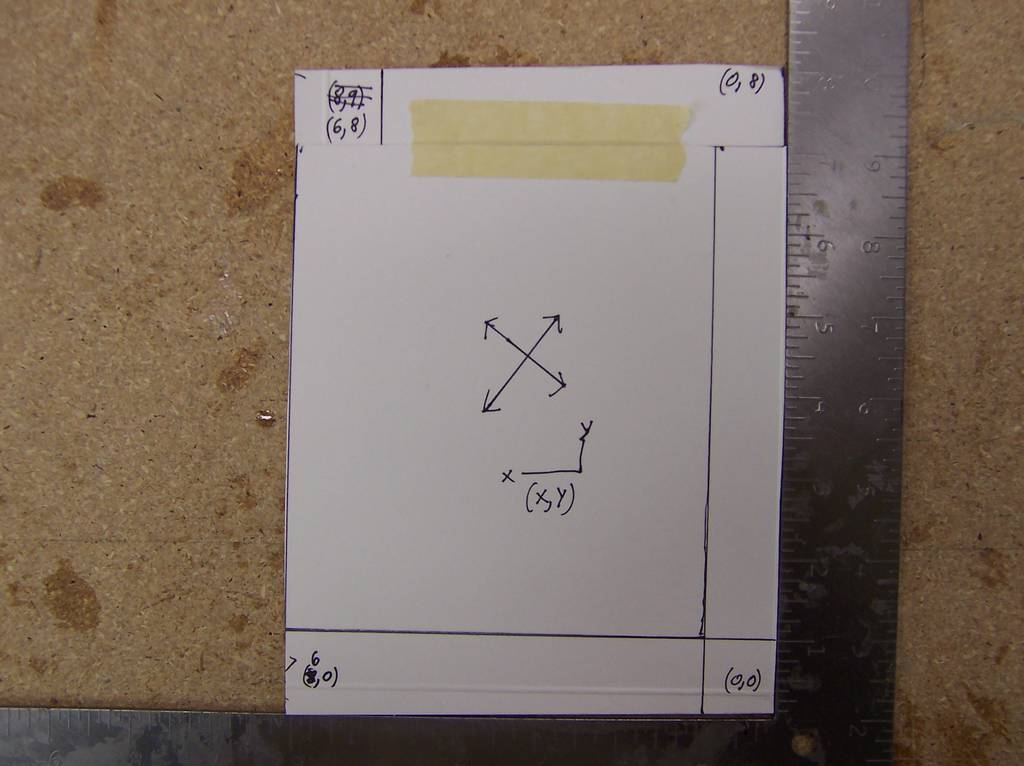
These layups took around 4 or 5 hours each. Before each layup, a template had to be made of the area to be fiberglassed. To make it easier for you, I took pictures of the templates I made. I also measured each template and placed X and Y coordinates for each transition point. This should allow you to duplicate my template and use it on your plane. My hope is that it will save you about 4 or 5 hours by having a starting point for your templates.
The X coordinate is shown in the traditional negative direction, but I have redefined it as a positive direction!!! Although it really shouldn't matter as you'll just get a mirror image of my template if you don't follow my "rule". The reason it doesn't matter is you will use one side of template for one side of the fuselage and then you'll flip it over to use on the other side.
The lines with arrows on each end show the BID orientation of the template. The lines with single arrows on them show the "X & Y" coordinate directions.
I like to make templates from posterboard. It is thicker than normal paper and can be easily moved around on the fiberglass to determine the best layout to minimize the amount of fiberglass used. Once a suitable positioning is found, it is easy to trace out the template using a felt tipped pen. The posterboard may be purchased at WalMart or art supply stores for about 50 cents for each 2 x 3 foot sheet.
Please let me know if you find the templates useful.
BID fiberglass template for the first part of the layup which goes from the forward landing gear bulkhead to the floor of the fuselage.
This template may be used on for both sides of the fuselage, however, each side is an opposite (i.e. use one side of the template for one side of the fuselage and the other side of the template for the other side of the fuselage).
The top of the template goes at the top of the forward landing gear bulkhead and the notch goes into the corner where the forward landing gear bulkhead, the fuselage side and the fuselage bottom all meet. The left side of the template is in the center of the fuselage and the right side goes along the side of the fuselage.
Template for the second part of the first layup.
An overall view of the location for the first layout. The template shown above would be for the left side of this photo (right side of the fuselage).
Close-up view of the first layout.
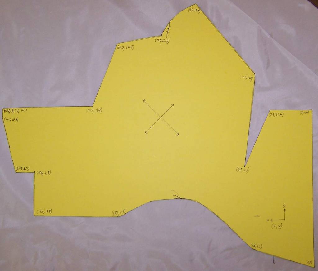
Template for the first part of the second layup.
The triangular notch in this template is for the corner where the vertical portion of the forward landing gear bulkhead, fuselage side and and the angled portion of the forward landing gear bulkhead all meet. The notch in the lower left side of the photo is for where the NACA scoop meets the aft landing gear bulkhead. The curved part at the bottom of the photo lays along the triangular pieces of plywood on the side at the bottom of the fuselage.
The template, as shown, is for the left hand side of the fuselage. Flip it over for the right hand side.
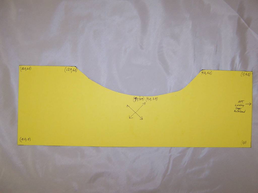
Template for the second part of the second lay-up.

View of the second layup.

Close-up of the second layup.
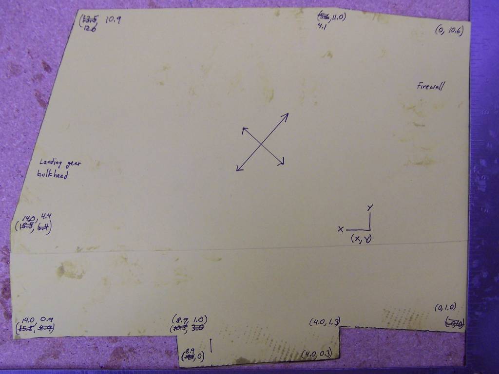
Template for the first part of the third layup
This layup goes from the aft landing gear bulkhead along the fuselage side and then wraps onto the firewall.
The left side of the template goes along the aft landing gear bulkhead. The middle of the template goes against the fuselage side. The right side of the template lays against the firewall. The tab at the bottom lays on the plywood on the bottom of the well formed between the landing gear bulkhead and the firewall.
The template as shown is for the right side of the fuselage.
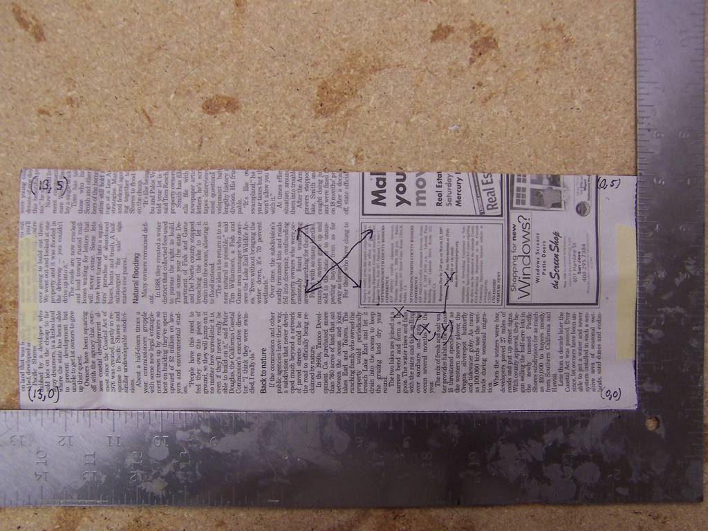
This is the template for the second part of the third layup. It goes down the aft landing gear bulkhead, over the plywood on the bottom and then up the firewall.
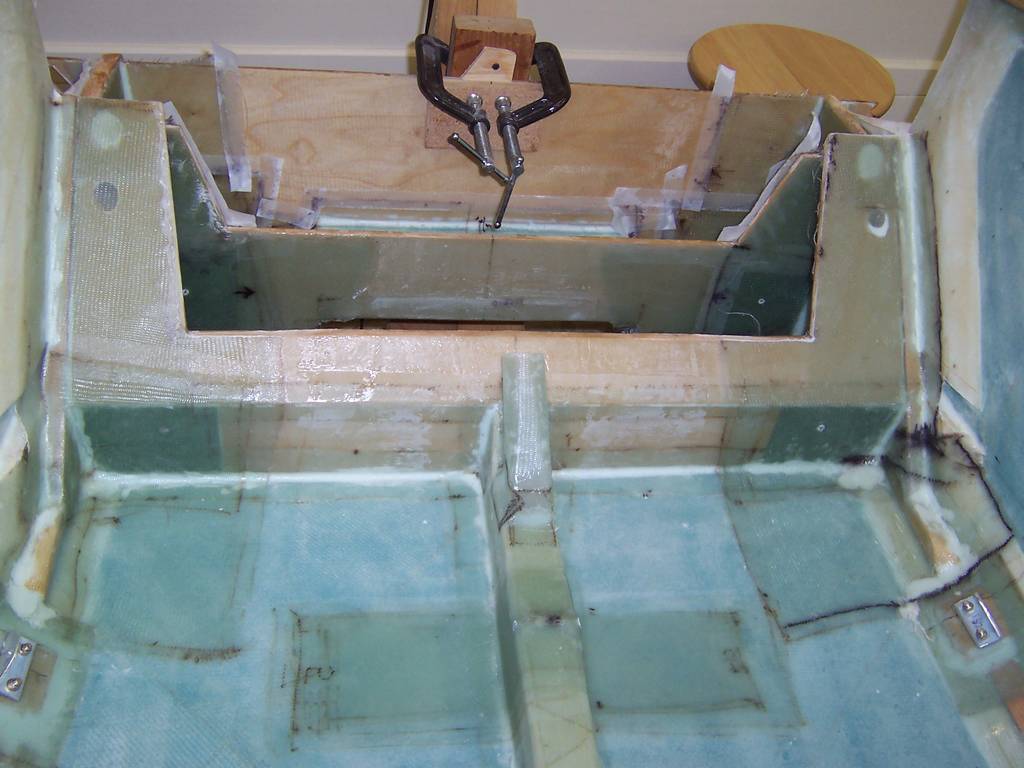
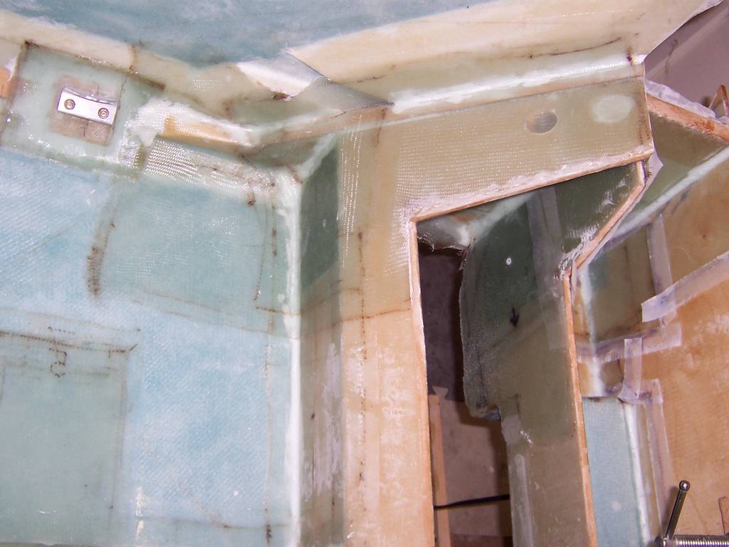
Overview of the third layup.
Closeup of the third layup.
Step 2 - Preparing the Landing Gear Strut for Installation
Multiple layups are done to provide additional resistance to twisting.
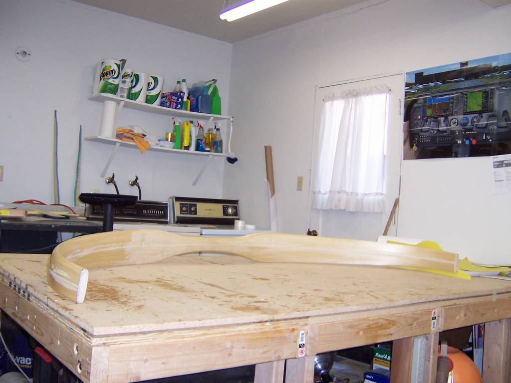
One concern I had was the amount of twist in the strut. When I received it, it would not lay flat on my workbench. You can see what I mean in the pictures below. I queried the Cozy Builders mailing list about it. Of the many responses I received, all except for one, said it was not a problem. Several builders even said their strut was also twisted. I now feel much more confident to forge ahead.
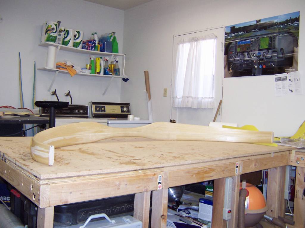
The leading edge of the strut is in contact with the workbench. A yellow piece of paper board was placed behind the strut to highlight the gap between the table and the strut.
Close-up of gap between the table and one side of the strut.
Close-up of the gap between the table and the other side of the strut.
The leading edge of the strut is the upper surface. Again, a yellow piece of paper board was used to the highlight the gap between the table and the strut.
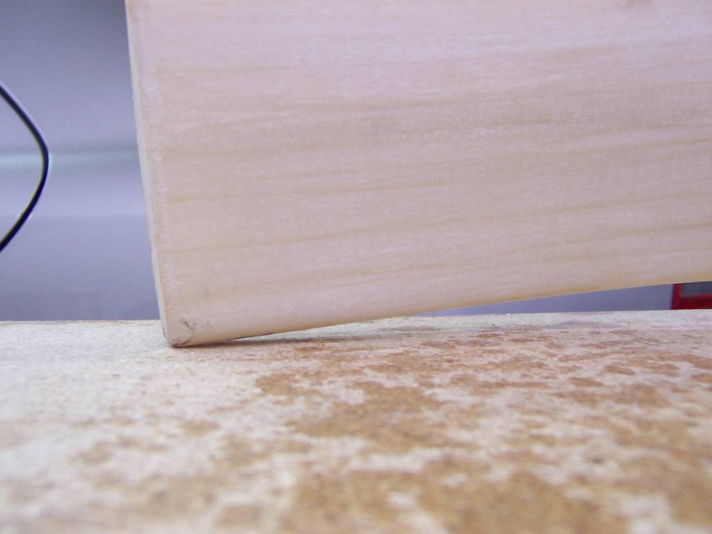
This side of the strut is in contact with the workbench.
The other side of the strut showing the gap between the table and the strut.
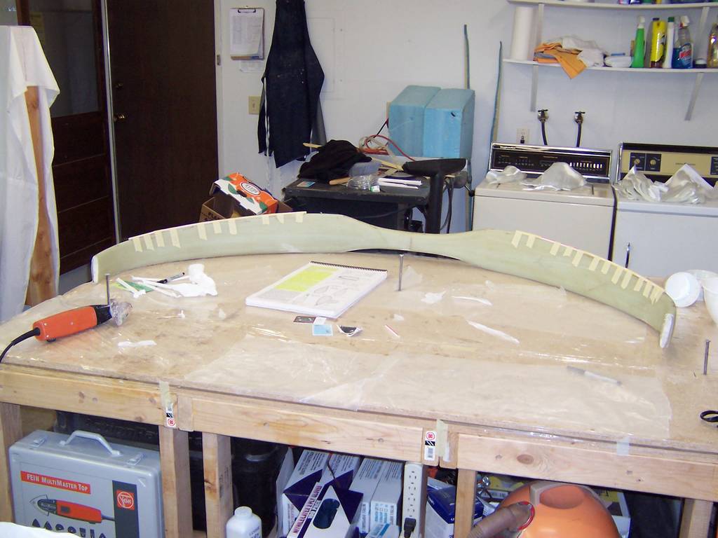
Attaching the McDonald's straws to the trailing edge of the strut.
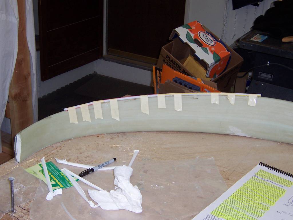
Left side of the strut with the McDonald's straws.
Right side of the strut with the McDonald straws.
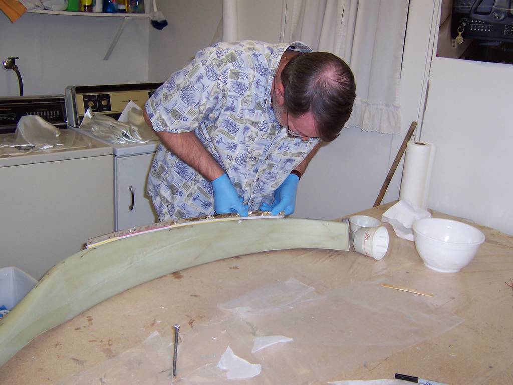
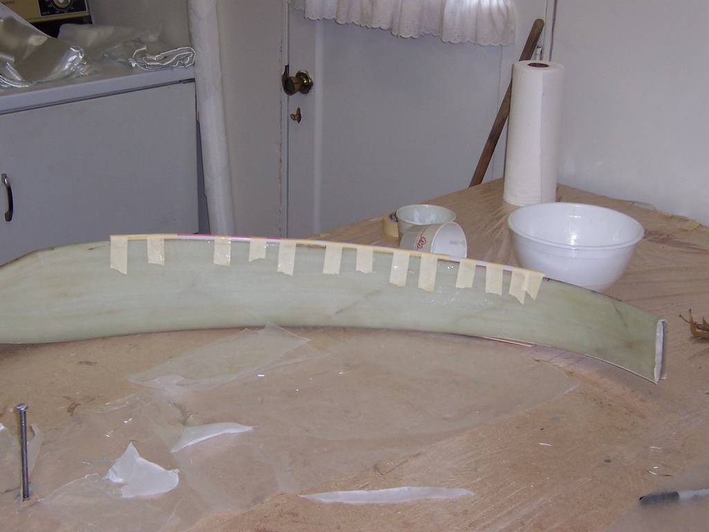
Jeff is attaching the aluminum tape to the trailing edge over the straws.
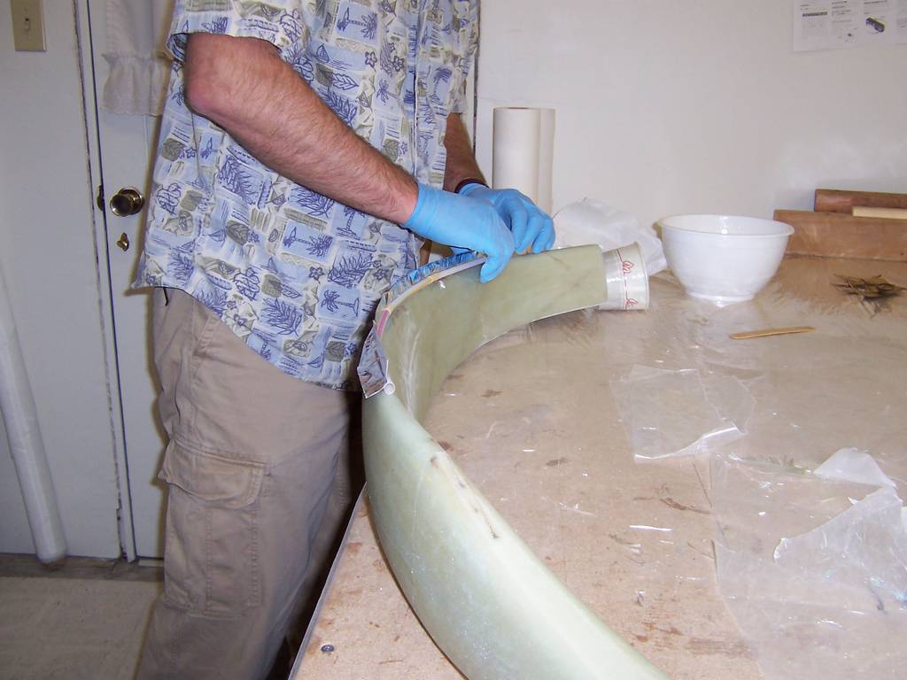
Close-up of Jeff attaching the aluminum tape to the trailing edge over the straws.
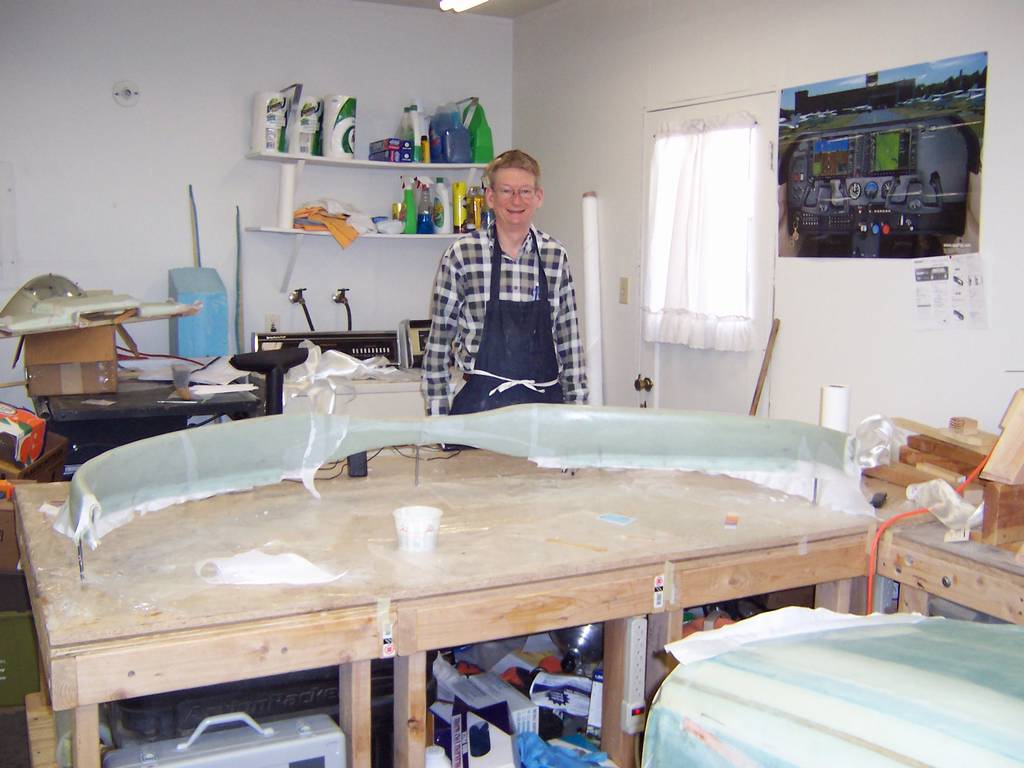
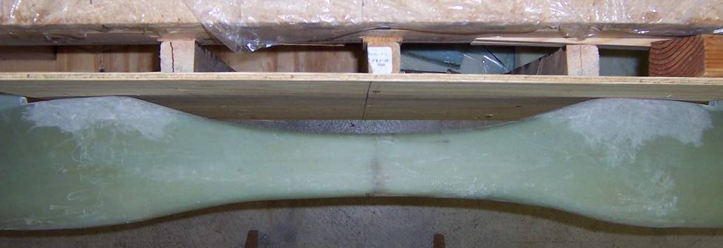
Neil and I have just completed the second, four-ply layup of UND on the strut.
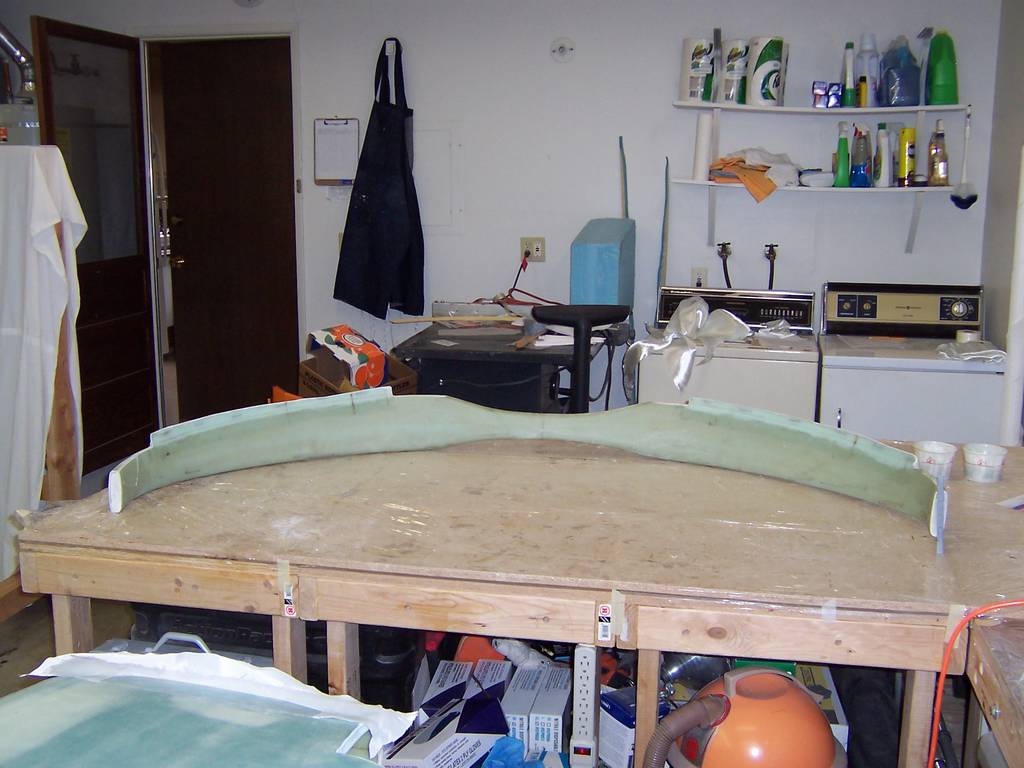
For this picture, the table has been leveled, however, the right side of the strut is above the the table.

Close-up of the right side showing it is about 1.2 inches above the table. The left side is in contact with the table.
Step 3 - Making the Attach Tabs and Installing the Landing Gear Strut
In this step, the attach tabs are added to the gear strut. The attach tabs will have bolts going through them to connect the strut to the fuselage.
Accuracy is very important as the fit is very tight. There is a lot of measuring and jig building to insure a proper fit.
A piece of plywood is attached to the end of the workbench. Many of the measurements are first made on the plywood, then transferred to the jig box to be built on top of the strut or to the workbench where the layups will be made.
It is important the bottom of each leg of the strut be level with each other. Since the floor in my work shop is not level, I had to place a 1/2 inch block under the left leg to make the two legs level with each other.
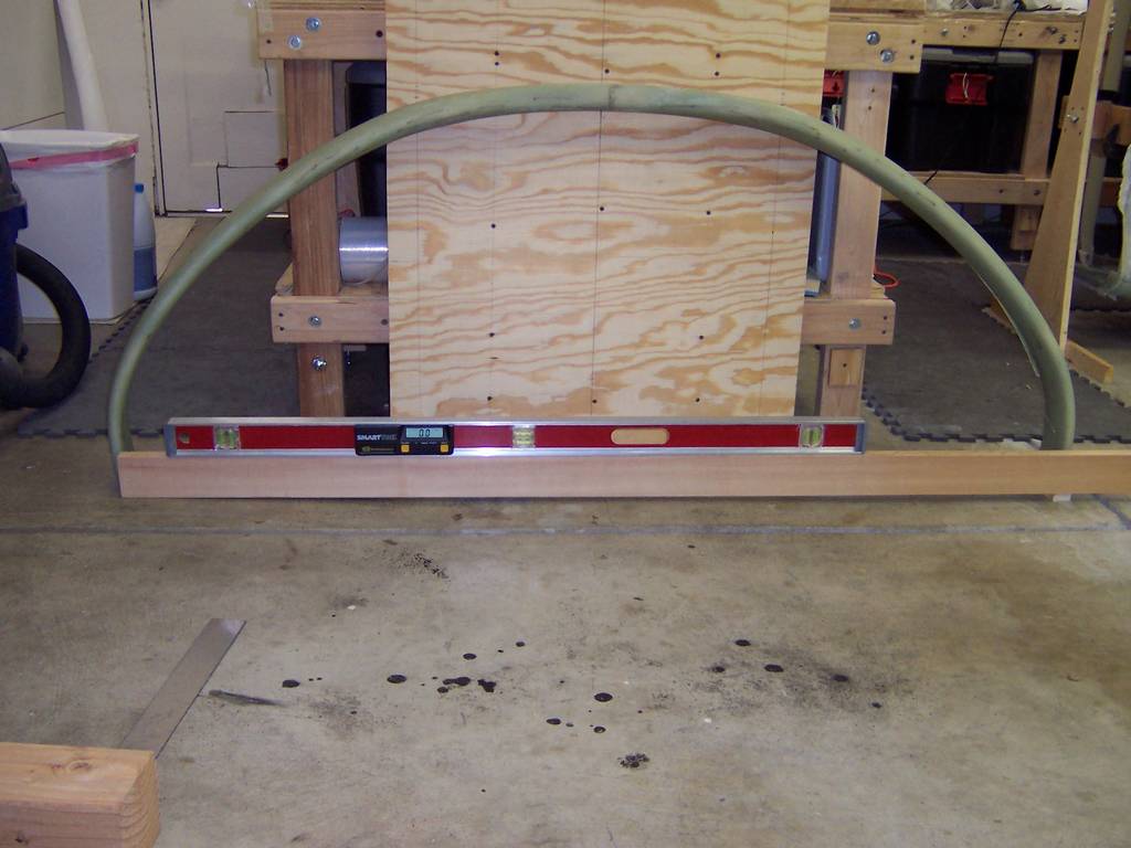
To check if the two legs are level, straight piece of wood was placed between the two legs.
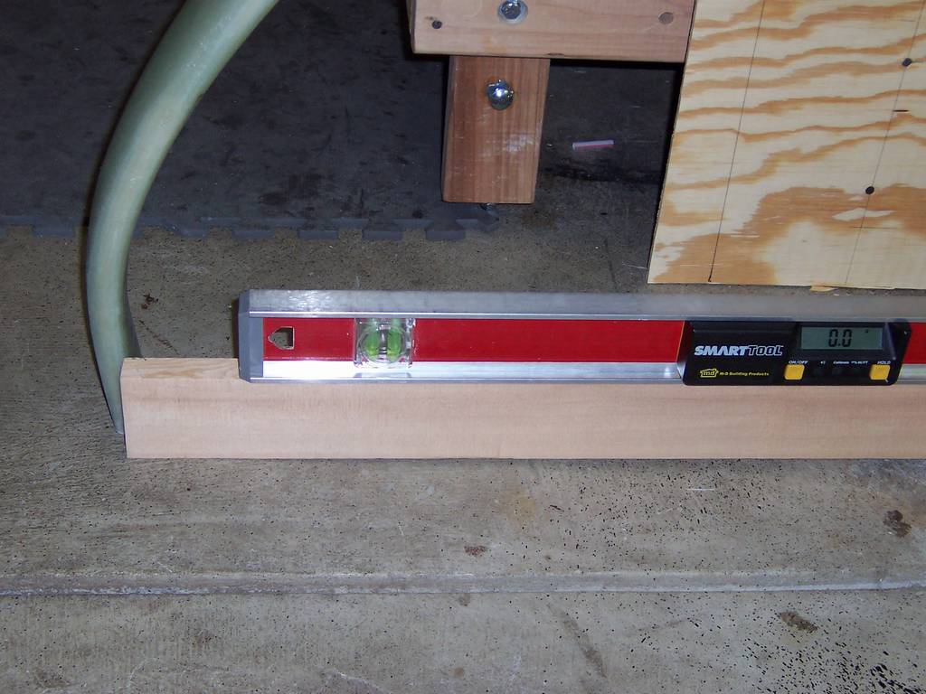
This is a close up view showing the left level point is 1/2 of the thickness of the strut. You can also see the digital level shows the ends of the two legs are level with each other.
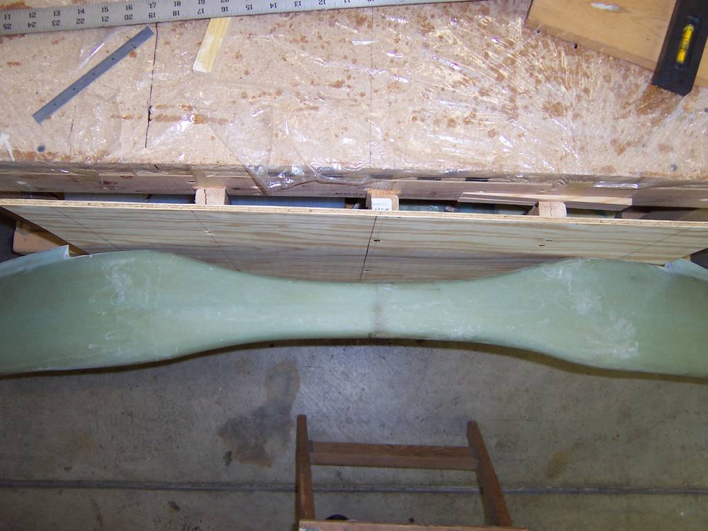
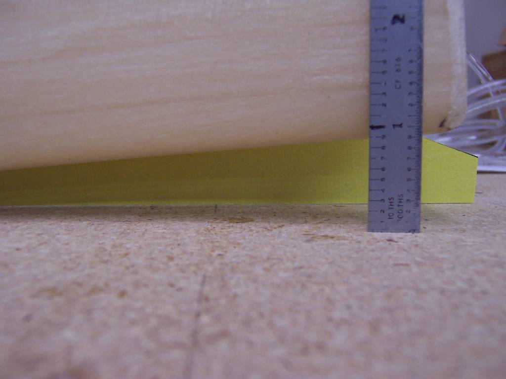
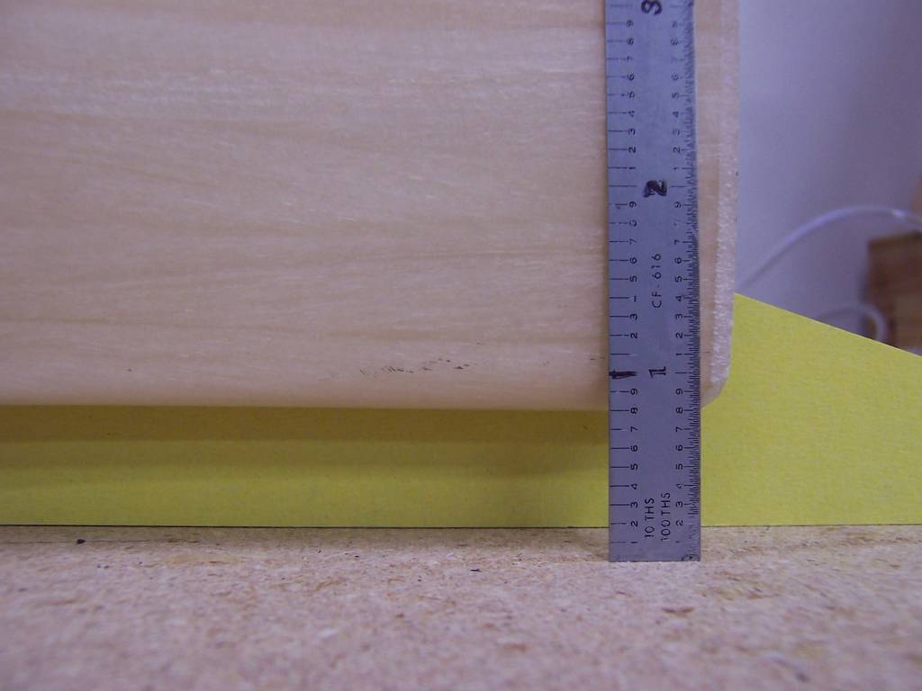
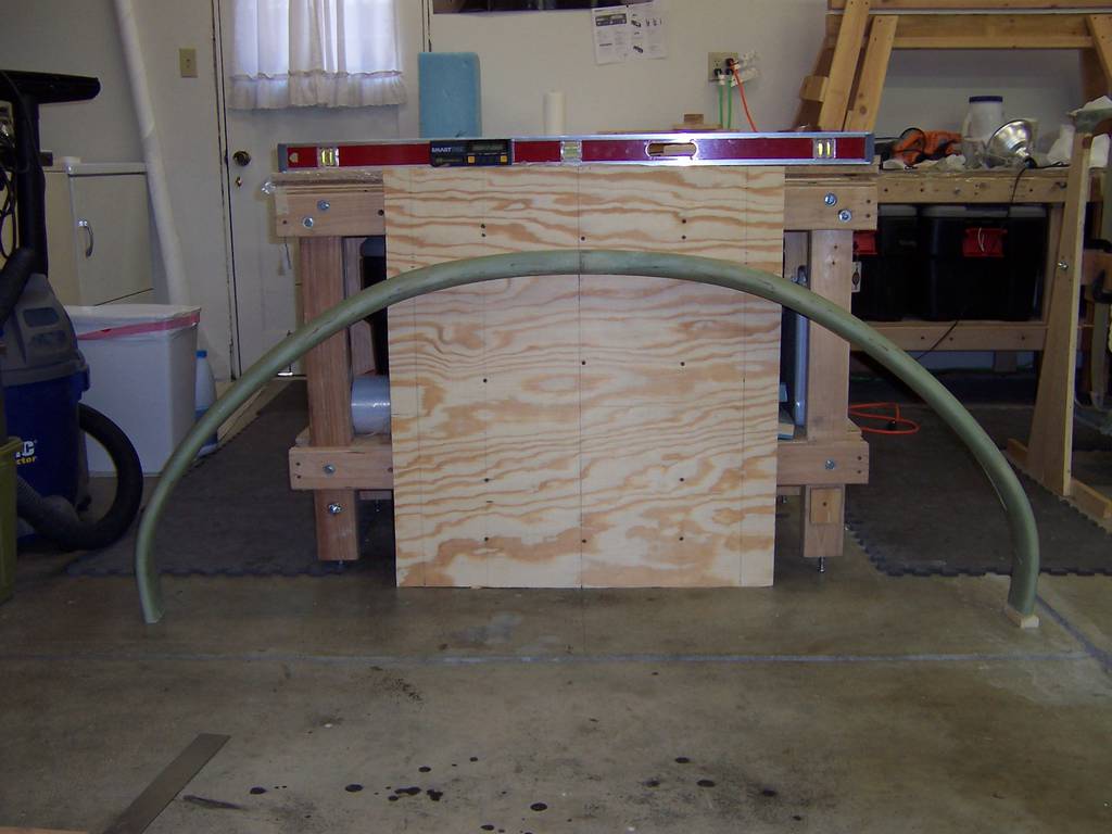
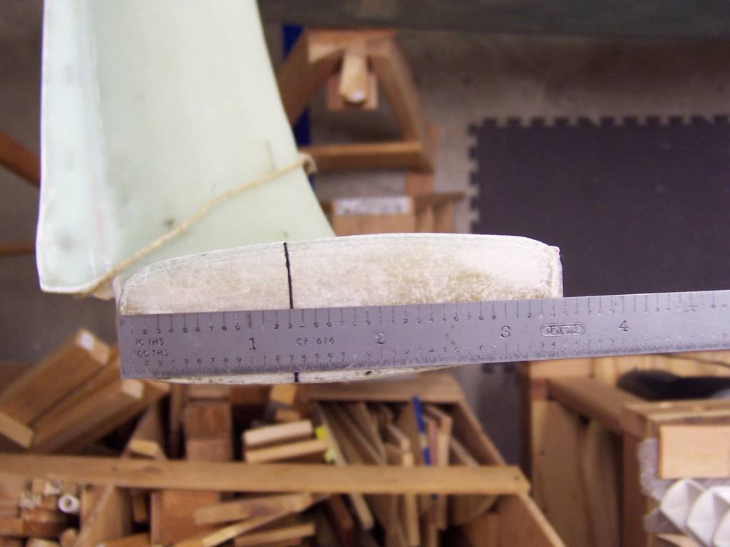
When the legs of the strut are placed 9.25 inches forward of the plywood, the left top edge of the strut is not in contact with the plywood. This is caused by a twist in the strut.
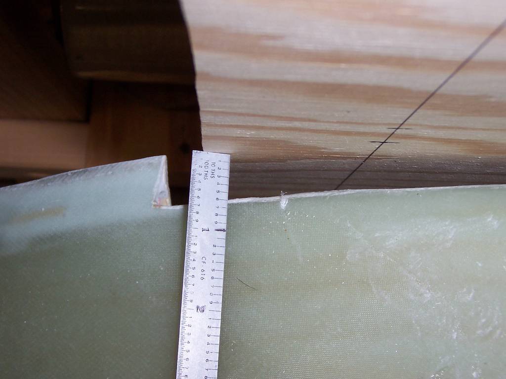
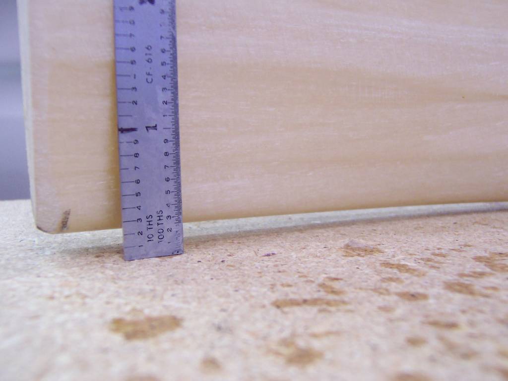
Here is a close-up view of the left side of the gap. The gap is 0.5 inches. The scale appears to show 0.6 inches, but this is due to parallax.

The closest the strut gets to the plywood on the left side is 0.3 inches, even though the scale shows 0.4 inches. Again, it is a parallax problem with the camera.
To correct the problem of the twisted gear, I took the advice of Ron Springer. According to the plans, the legs are to be placed 9.25 inches forward of the plywood. With my gear strut, when I did this, there was a huge gap on the left side between the top of the strut and the plywood. To reduce this, I placed one gear leg in front of the 9.25 inch reference line and the other behind it. The legs were placed an equal distance in front of and behind the line. When I did this, the top of the gear was very close to the plywood on the left side and touching on the right side, as shown in the above photo.

The left gear leg was placed 1/2 inch behind the line.
The right gear leg was placed 1/2 inch in front of the line.
The block under the gear leg is needed since the work shop floor is not level.
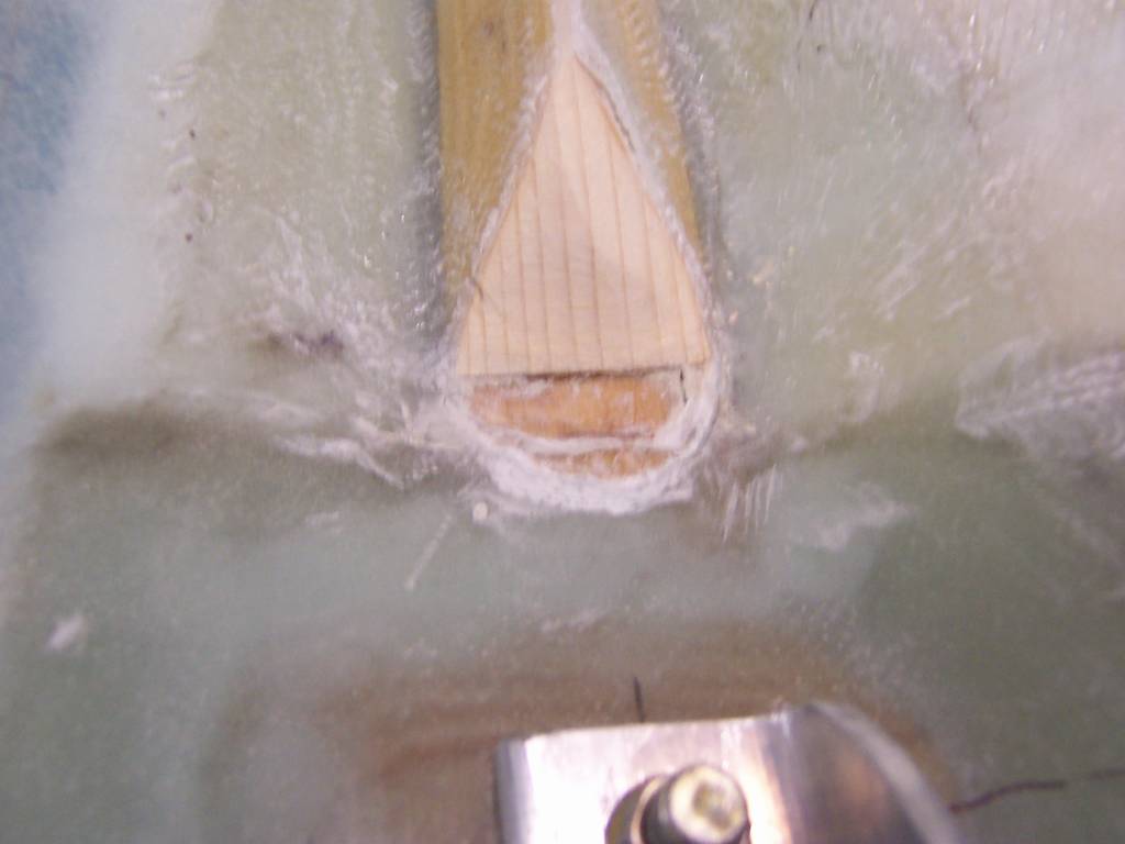
Leading edge of strut with the jig box bondo'd to the table. Support braces were also bondo'd to the table and to the strut.

View of the trailing edge of the strut.
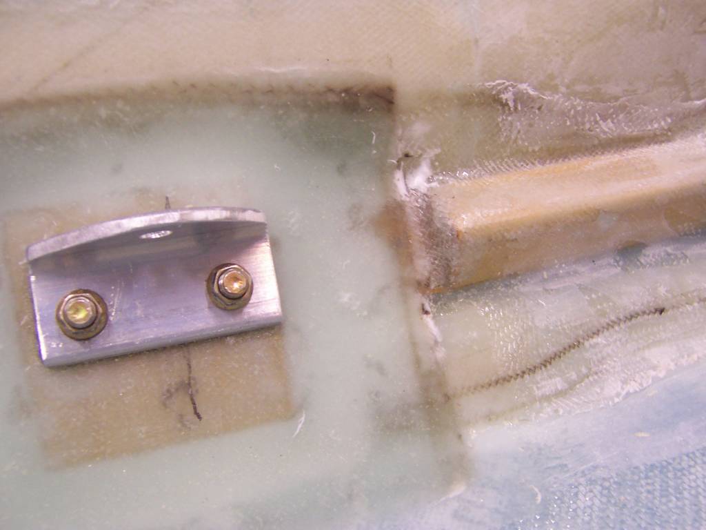
Close-up of the jig for the trailing edge attach tab.
The other trailing edge attach tab location.
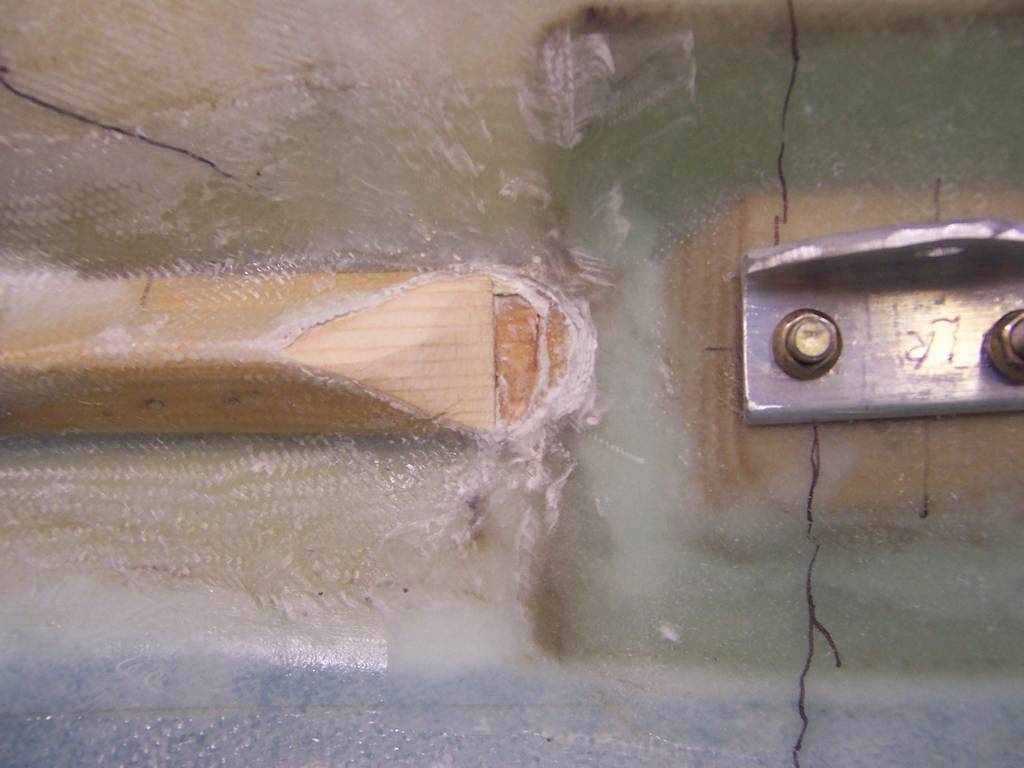
The leading edge of the strut and jig box.
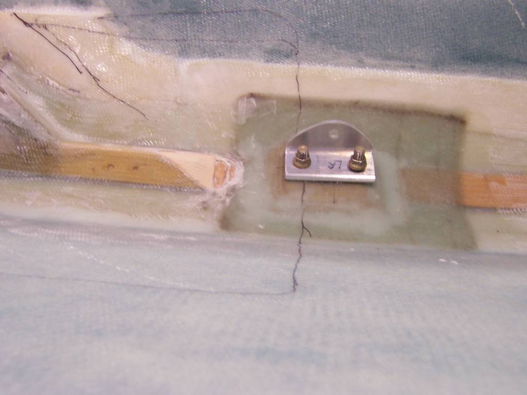
Leading edge attach tab location.
The other leading edge attach tab location.
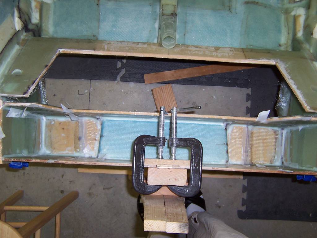
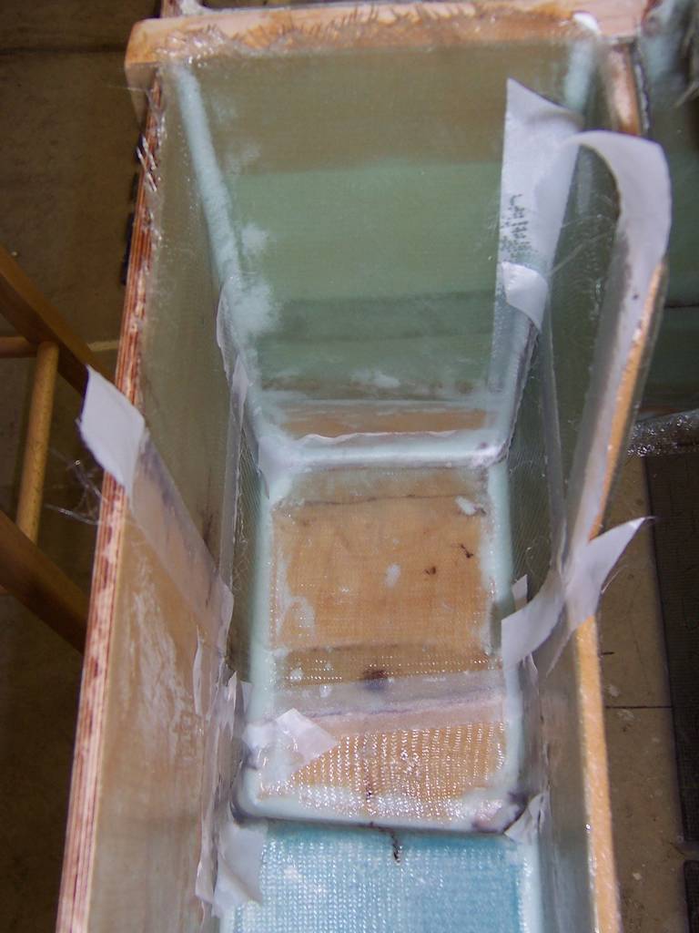
After the tabs are made, MG1 and MG2 are cut and drilled from 1/8 inch and 1/4 inch thick aluminum. The purpose of these are to align and support the rods that are placed through the landing gear tabs. They are attached to both sides of each of the landing gear bulkheads. Once they are attached and the alignment checked again, the 1/4 inch center hole is enlarged to 5/8 inch. I had purchased the LongEze spot facing tool when I originally ordered my miscellaneous tools in July of 2005. This tool is made from steel and it dulls very easily. During the drilling, as soon as the bit began to get hot to the touch, I would stop and let it cool down. The first hole took me around 6-hours of on and off drilling. I then had to sharpen the bit before I started on the second hole. As I write this, I am about 1/2 way through the second hole.
Spot Face Cutting Tool (from the "Tips and Techniques" section)
In chapter 9, I had to drill holes for the landing gear mounting bolts. The ones through the landing gear bulkheads were 5/8" inch and went through a metal plate, then through 1/4" of fiberglass then through another metal plate. The holes in the landing gear tabs were 3/4" through fiberglass only.
The plans recommend using a specialty tool called a LongEze spot facing tool. This tool is expensive and to be honest, very difficult to use. I spent many hours drilling the first hole. For the second hole, I asked my friend, Jeff Owen for some advice. Jeff was a machinist in a previous life and he is currently designing the engine installation for me. He helped me with one of the 5/8" inch holes in the landing gear bulkhead. After a couple of hours, he had had enough! He knew there must be a better way. So, he examined the bit and decided to make some modifications to it. After the modifications, the bit went through the metal like a hot knife through butter. It also worked well on the fiberglass.
The problem with the bit appears to be with the four very small pointed tips on the edge of the bit. These tips are there to create a circular channel in the fiberglass. Then, when the main part of the bit starts cutting the fiberglass, it doesn't tear it. Unfortunately, due to their small size, they dull very quickly. Jeff removed the tips and then the bit went through both the metal and fiberglass very quickly. After removing the tips, the time to drill the holes went from 6-hours for the first hole to 2-hours for the second hole (the tips were removed half-way through this hole), to about 15 minutes for the two remaining holes. I consider this modification a success!
Removing the tips does not appear to be a problem for the holes on the landing gear bulkheads as both sides are faced with a metal plates. However, on the landing gear tabs, it could be a problem. So, what I did was to start the holes using the 3/4" spot facing tool before it was modified. I drilled each side of the two holes in the landing gear tabs till tips had created a circle around the outside of the holes down to the depth of the tips. Then Jeff removed the tips and we completed drilling the holes out. Doing this really speeded up the process of drilling the holes.
One word of caution, this tool is also used to drill the holes for the wing bolts. Now that these tools have been modified it will be interesting to see how they will work on the rest of the project.
Instructions on how to modify the bits are shown here:
Modifying the Spot Facing Tool
Step 4 - Making the Landing Gear Cover
Making the landing gear cover was pretty easy and a lot of fun. There was a since of accomplishment upon completion of the cover.
I used the Wayne Hick's method of making the cover, instead of the plan's method. I did this as there have been a lot of complaints at how difficult it was to get the fiberglass to lay down in the depressions at the landing gear bulkheads. Also, adding the aluminum slugs to the bulkheads are difficult and drilling the holes in them through the landing gear cover is a hit or miss proposition as you cannot see the slugs when you are drilling. Wayne's method does away with the depressions and it does away with blindly drilling holes hoping to hit the slugs.
With Wayne's method, the cover is built and then a shelf is formed under the the landing gear cover to hold it in place. Holes are then drilled through the cover and the shelf. Nut plates are then attached under the shelf and your done. No guess work involved. I'm very pleased with the results.

Foam is being put in place to make the landing gear cover. The 3/8" PVC foam is supported by wood blocks which I temporarily attached to the landing gear bulkheads using hot melt glue.

Another view of the wood blocks. After taking this picture, I placed foam over this open area. Next, a 2-BID layup was done over the foam.
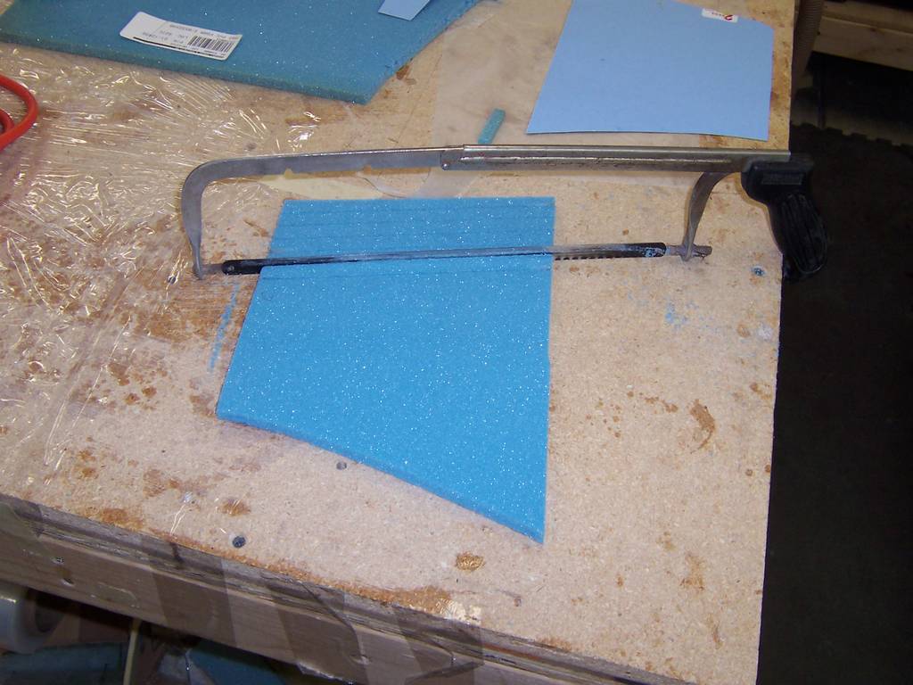
To get the foam to follow the curving sides of the fuselage, I made some diagonal cuts in the foam. This allowed the foam to easily wrap around the side.

I have now jumped ahead a few steps. Sorry, I didn't take any pictures of the intermediate steps of attaching wood braces to the cured bottom of the cover. Then it was removed from the fuselage. The foam was cut back about an inch all the way around. Next the bottom was fiberglassed with 2 layers of BID over the entire bottom and then an additional 4-layers along the edges to provide support for the screws which will be used to hold the cover in place.
This photo shows the outside of the completely fiberglassed cover.
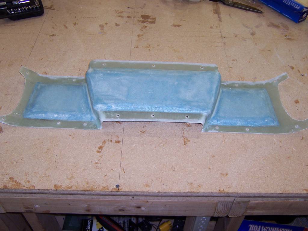
This is a photo of the inside of the completed cover.

Again, this is another big jump ahead showing the completed cover on top of the fuselage. If you look closely, you can see the 6-layer BID shelf in place to hold the cover in place.
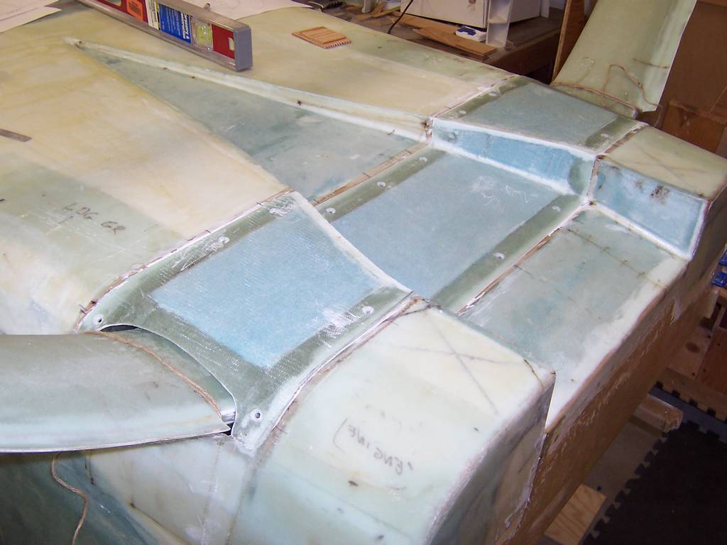
The completed cover in place. All that is left is to attach the nutplates to the bottom of the shelf. I'll have to wait till I can borrow an rivet squeezer to complete this step.
Step 5 - Installing Axles, Brakes, and Brakelines
I am not going to use the Cleveland brakes and axles recommended in the plans. Instead, I will be installing the Matco brakes and axles. This seems to be the current concensus amoung Cozy builders.
The reasoning is the Matco's have a much higher stopping power than the Clevelands. According to studies done by various individuals, the Clevelands will not meet the FAA recommended stopping power. I believe the Clevelands were used for a couple of reasons. First, they are the same brakes used on the VariEze and the LongEze, so it was convenient to use them on the Cozy also. However, the Cozy is a much heavier aircraft. Second, the Matco brakes were not available when the plane was designed and the Clevlands were the best available.
With the introduction of the Matco brakes, it makes sense to use them. However, the installation is different from the Clevelands. The main difference is the shape required for the bottom of the landing gear strut to accomodate the Matco brakes.
Several builders have devised templates for the desired shape of the bottom of the strut. I have found two that were available. One is from Jim Springer and the other is from Bernie Siu. After studying them both, I am going with Bernie's template. His matches my brake caliper a little better.
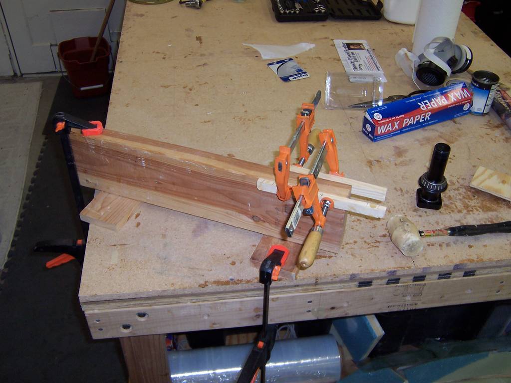
I needed to remove the axle from the Matco wheels and brakes. I was able to get to remove the axle, but I could not get the inside wheel bearing off. It was on so tight I could not remove it by hand. When I looked at other builder's web sites, they all had pictures showing the axle without the wheel bearing, so I knew it must come off. I fretted about this for a couple of days before deciding to get physical.
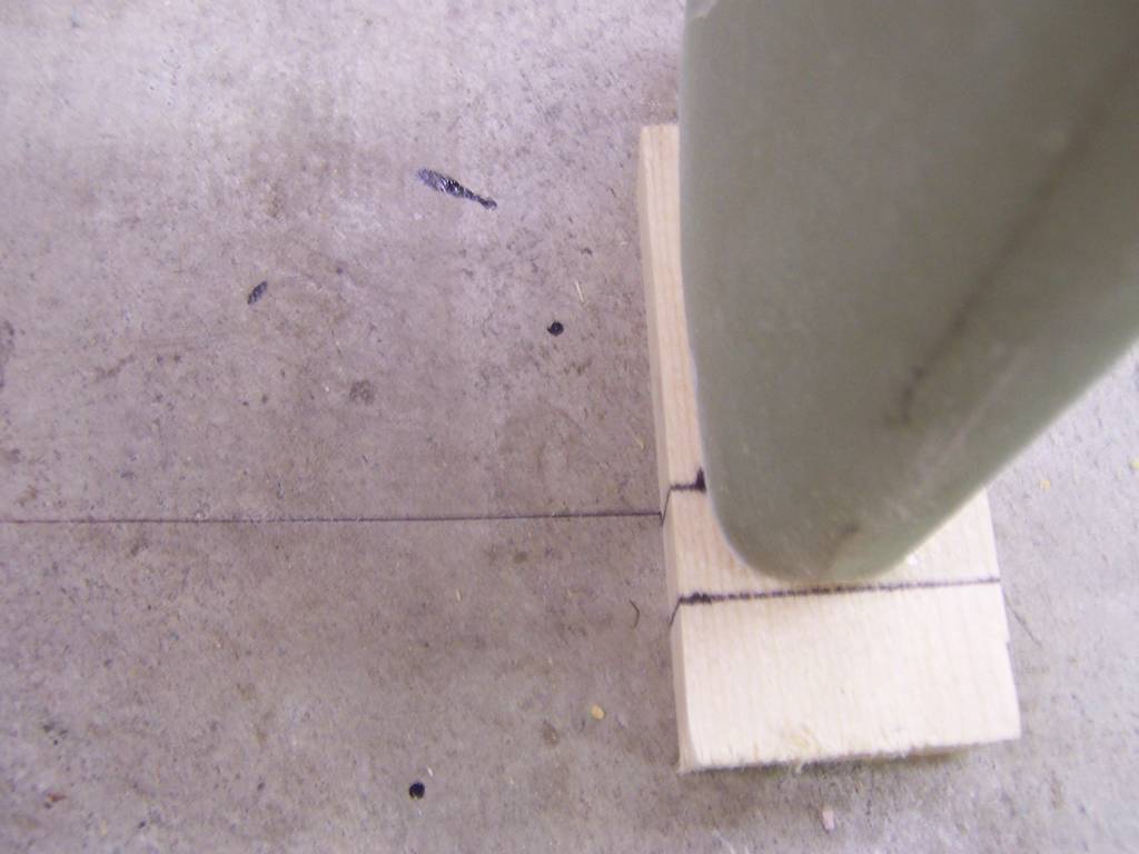
I built the contraption shown in this picture. The two sticks are to support the wheel bearing. in this
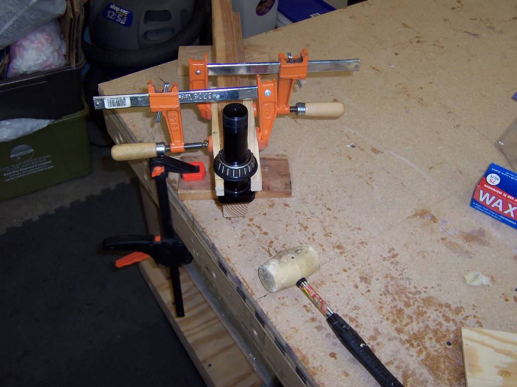
Here is the wheel and axle on the support I built. I tapped the axle very lightly with the mallet and to my surprise...
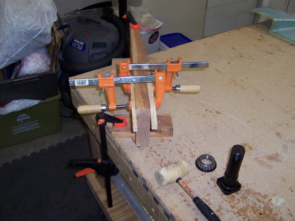
...the axle dropped right off! It was so simple and didn't require much of a tap at all. OK, this problem solved, on to the next!
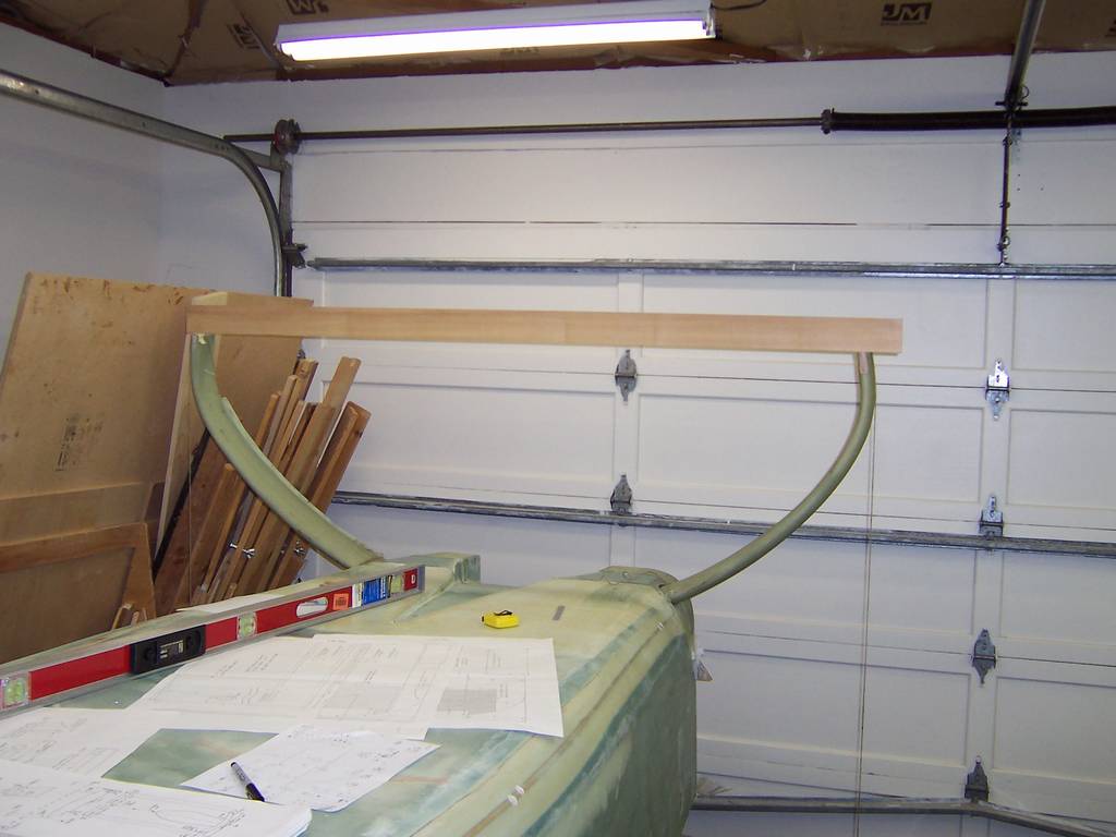
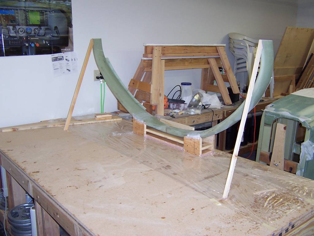
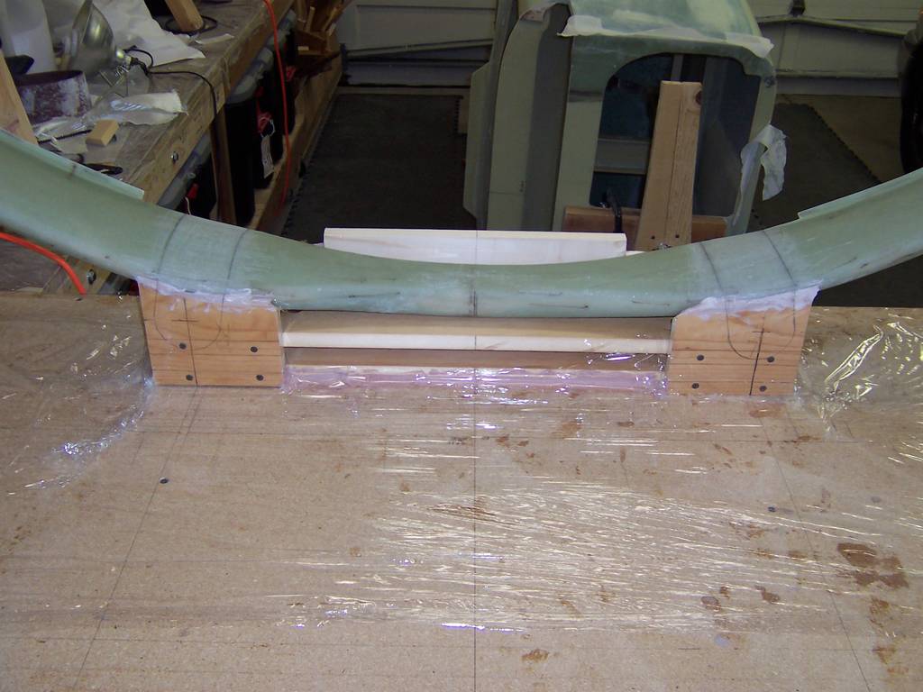
General view showing the landing gear strut in place. The 2x4 across the top is give me a place to put the level to check it out. The two legs are level to within 0.1 degrees.
As noted earlier, my strut is twisted. From what I have read on other builders web sites, I believe mine is twisted a little more than everyone elses. This has not bothered me as the plans and everyone keeps saying there are plenty of places to fix the problem. Well, I'm now down to the final steps and very little correction has been made. My strut is a bit skewed between the landing gear bulkheads to help reduce the problem, but I couldn't skew it enough to completely solve the problem.
As can be seen in the pictures below, I can mount the axles at F.S. 110, but that may be putting them a bit close to the edge of the strut. If I mount them in the center of the strut, then one side will be at F.S. 109.6 and the other will be at F.S. 110.42. This is a 0.82 inch difference. This is probably not a problem.

Right Strut: As seen above, F.S. 110 is 2.15 inches from the aft of the strut. The center of the strut is at F.S. 109.6.
Left strut: This is the other strut. F.S. 110 is 1.33 inches from the aft of the strut. The center of the strut is at F.S. 110.42
I did not like having the axle so close to the end of the right strut. So, instead of mounting the right side axle at F.S. 110, I mounted it at F.S. 110.5. This will put it closer to the center of the strut.
The axle for the left strut is mounted at F.S. 110, which is where the plans specify. I do not believe the 1/2 inch difference between the sides will be a problem. However, I must take this into account when calculating the center of gravity of the aircraft. It will not affect the weight and balance calculations made before each flight.

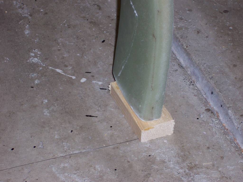
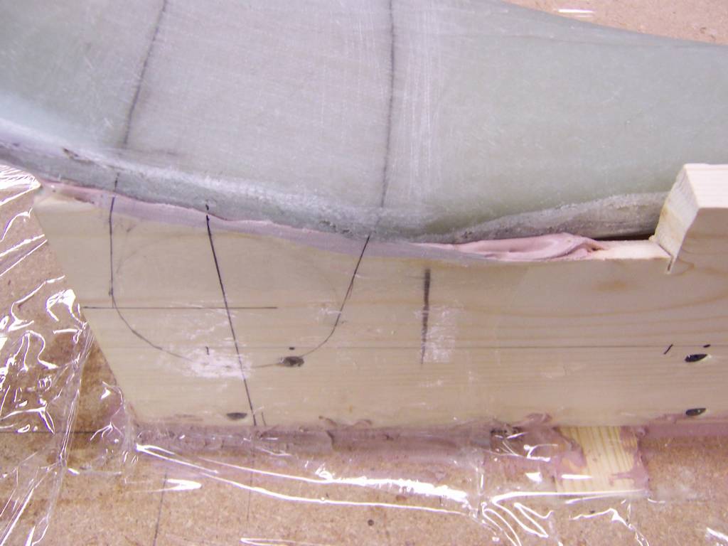
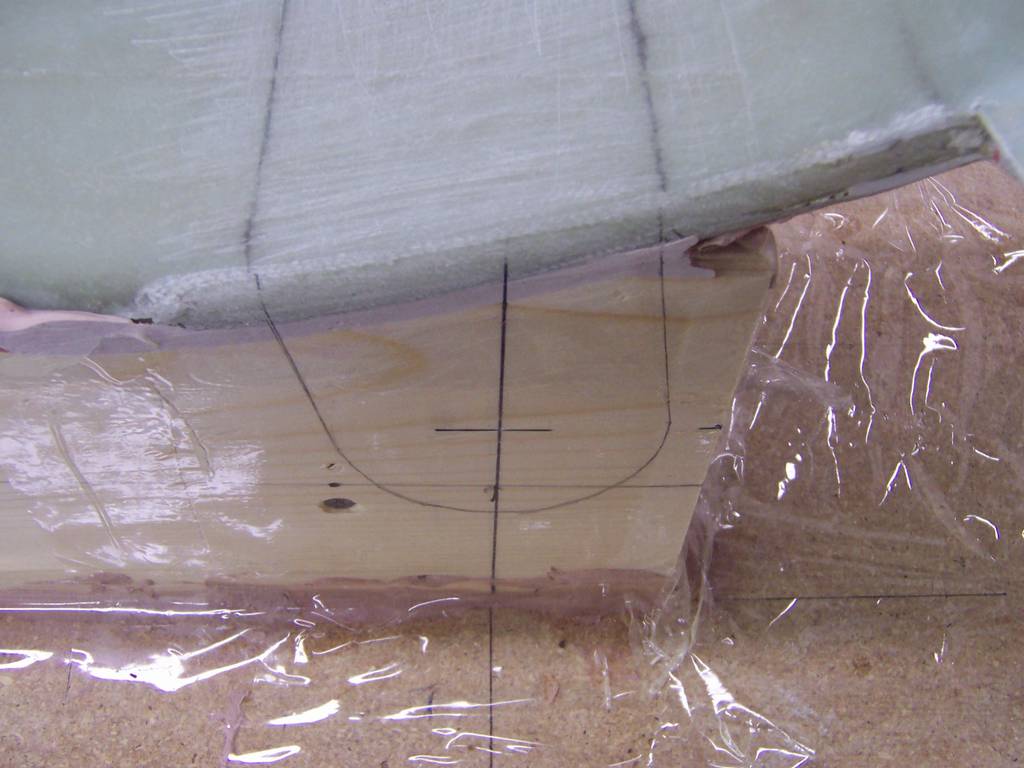
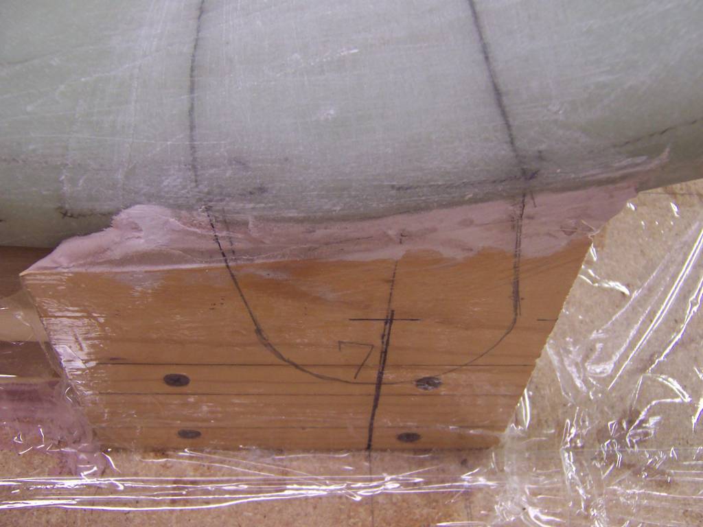
These are the slightly modified templates from Bernie Siu which I used to trim the end of the strut to provide clearance for the Matco brakes.

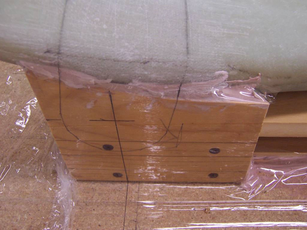
Right strut showing outline of the trimming needed for the Matco brakes.

Left strut showing outline of the trimming needed for the Matco brakes.

Preparing to drill the axle mounting holes in the strut.

Preparing to drill the holes in the aluminum backing plate.

Right strut with the axle, wheels and brakes mounted. This view is looking forward

Left strut with the axle, wheels and brakes mounted. This view is looking forward.

Right strut with the axle, wheels and brakes mounted. This view is looking aft.

Left strut with the axle, wheels and brakes mounted. This view is looking aft.

Overall view of the project.
Step 6 - Constructing the Landing Brake
In this step the landing brake is cut out of the fuselage bottom and then hinged to the bottom. Then, in a future chapter, a manual system is built to raise and lower it. I have decided, like so many other builders before me, to use an electric motor to raise and lower the landing brake. The reasons are for a simpler and a lighter installation.
The first step was to find an electric actuator to do the job. This was easy as several builders are using the 4" Warner Electrak 1 Linear 12 Vdc Actuator model S12-17A8-04. It was very comforting to see everyone using the same one.
After searching for this actuator on many web sites, I found the best price at: Power Drives, Inc.. However, just before I was about to purchase it, I decided to see if there were any on eBay. To my surprise, I found two being auctioned. I bid on both and won one of them.
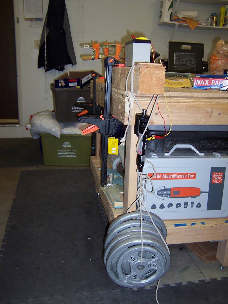
Testing the landing brake actuator I purchased on eBay. There are 65 lbs of weights attached to it. The unit is rated for 75 lbs.

The actuator sucessfully lifted the 65 lbs. It works!
Cutting the landing brake out was very difficult. After finally getting it out, I took a closer look to see what the problem was. It turns out I had used excess micro to glue various sections of the bottom foam together. Some of this micro had seeped to the landing brake, thus gluing parts of it firmly to the bottom foam.

Front view of landing brake cutout.

Side view of landing brake cutout.

Aft view of landing brake cutout.

Landing brake after it has been removed from the fuselage. The hinge and plywood support have been installed.

Aft view of installed landing brake.

Forward view of installed landing brake.

Aft view of opened landing brake.

Forward view of opened landing brake.

Actuator attached to landing brake. The braket is made of fiberglass. It is similar to the one described by Wayne Hicks.

Actuator attached to landing brake. The braket is made of fiberglass. It is similar to the one described by Wayne Hicks.

Original installation of the landing brake actuator attached to seatback before it was modified. This was accomplished using the Wayne Hicks' method.

Original installation of the landing brake actuator attached to seatback. This was accomplished using the Wayne Hicks' method.

This is the re-worked installation of the landing brake actuator. Jeff and I decided to move the fuel selector valve back to the plans position. When we did this, there was interference where the fuel lines came out of the seat back brace and the landing brake actuator. To solve this problem, the landing brake actuator bracket was made larger and moved further aft along the back of the seat back.

We also, slightly, changed the mounting method of the backet. We made 1/8" aluminum backing plate the same size as the bottom of the bracket. Then we mounted two nut plates on it. We carved out some holes on the back of the seat back for the mounting plates to nestle into. Then we flox'd the backing plate to the seat back. We did not cover it with any BID.

Click above picture to see the landing brake opening and closing. The format of the movie is "mov". On a Windows machine or a Macintosh, QuickTime may be used to view it.
Chapter 9 is Done!

Jeff (left) and Brian (right) checking out the plane.
Chapter 9 has been a difficult and long chapter. I had orginally thought it would take 2-months to complete. It has actually taken 7-months. The main reason was the amount of research that was needed to complete the chapter. This was further complicated by having a lot of twist in the landing gear strut and worrying about how it would work out. Another prime contributor to it taking so long was the number of small layups which needed to be completed. This meant working on the plane for a couple of hours and then having to wait a day for the layup to cure before working on the next layup. I'm glad this chapter is behind me.
Before continuing to the next chapter, I'm planning on spending about 2-months researching and building a propeller. One is needed to test the engine which is currently on a test stand. Engine start should be some time in the Spring of 2009. Once the propeller is completed, then I'll start on chapter 10, building the canard.
As luck would have it, I was offered a propeller to use for testing the engine. However, the engine modifications are now on hold till we actually need the engine, which will be a few years from now. The propeller making has also been put on hold till the end of the project. Chapter 10 may now be started!