Page updated on:
January 24, 2021
Mazda 13B Rotary Engine Project SOLD
January 2, 2021
Today, the engine project was sold to Chad of Montana. He and his wife, Heather, drove 17 hours from Montana in a SUV. We loaded up the engine and they drove back, arriving home the next day. What a marathon trip they had!
I wish them the best of luck with the engine and hope they have as much fun working on it as Jeff and I did!
June 30, 2020
I'm sad to say my Cozy project has come to an end. The project has been a TON of fun, but has reached the point I can no longer continue. Also, my good buddy, Jeff, who was the expert on the engine is moving out of the area. I don't have the necessary expertise to finish the engine project.
I'm very excited to be able to pass this wonderful piece of technology on to another enthusiastic builder. The work Jeff and I have done is top notch. Jeff brought many years of experience to the project with his background in engines, his welding skills and most importantly, his design engineering skills. The next owner of this engine is going to find many exciting possibilities along with a well thought out design. Come with me as we take a tour of this rotary engine project.
I do want to highlight one item included in the sale. It is the legendary Real World Solutions (Tracy Crook) bombproof planetary PSRU. 2.83 to 1 ratio RD-1c (the strongest he built). I purchased it new and it has never been run. It comes with a Mazda mounting plate and flywheel isolator/adaptor. Easy to mount on most engines.
This section is all about the engine and what is included in the sale. The next section is the original webpage showing our progress in this conversion.
I'm asking $8,000 for the entire installation (negotiable).
Check out all the items included with the sale:
|
|
Let's take a look at some recent photos. The tour starts at the front of the engine. Proceeds clockwise around the engine. Then we take a quick look at the firewall, engine controller, test control panel and wind up with a couple of shots showing the original components removed from the engine. Yes we saved all the accessory parts that were removed.
Let's get started!
Click on any picture to get a larger view.
-010.jpg "Click for larger view")
This is the beast! The engine, the firewall and the engine test stand. The firewall is the exact size of a Cozy firewall. We wanted this so it would be easy to know the best location for the various accessories.
-020.jpg "Click for larger view")
Propeller Speed Reduction Unit (PSRU) is the RDC-1 from Real World Solutions, which is Tracy Crook's former company. His PSRU is one of the best around. It is based on a Ford truck transmission and is one of the most reliable units available.
-022.jpg "Click for larger view")
This PSRU is geared for 2.83:1 to keep the propeller tip speed from exceeding the speed of sound when the engine is reving at 7,000 RPM. The "114C" stamped on the case is serial number and the version.
-025.jpg "Click for larger view")
Just below the PSRU is the Starter.
-026.jpg "Click for larger view")
This side of the engine is where the spark plugs are. Notice there are two spark plugs for each rotor. This offers redundancy in case one fails.
-027.jpg "Click for larger view")
The back of the engine. The two items here are the alternator on the left and the throttle body on the right.
-028.jpg "Click for larger view")
The throttle body is connected to our own designed air box. This was built for testing purposes. Unfortunately, the design we used will not allow the engine to idle very well. As long as the engine is running at 50% power or higher, this box will work fine. It is only during idle there may be problems.
-030.jpg "Click for larger view")
The alternator is a stock Mazda accessory. I *think* it is rated at 70 amps.
-035.jpg "Click for larger view")
This side of the engine has both the intake ports (upper) and the exhaust ports. The upper intake tubes are shown here.
-040.jpg "Click for larger view")
One item we never got around to designing was the exhaust tubes. We do have a metal frame, which is attached to the engine and is removeable, on which to mount the tubes.

This is the Cozy Girrrl Mazda 13B mounting bed for the engine and the Cozy Girrrl 13B engine mount, before they were put on the engine. The mounting bed is attached to the bottom of the engine but above the oil pan. It is then attached to the engine mount using the rubber dampers on the 4 corners of the mounting bed, as shown in this picture.
-060.jpg "Click for larger view")
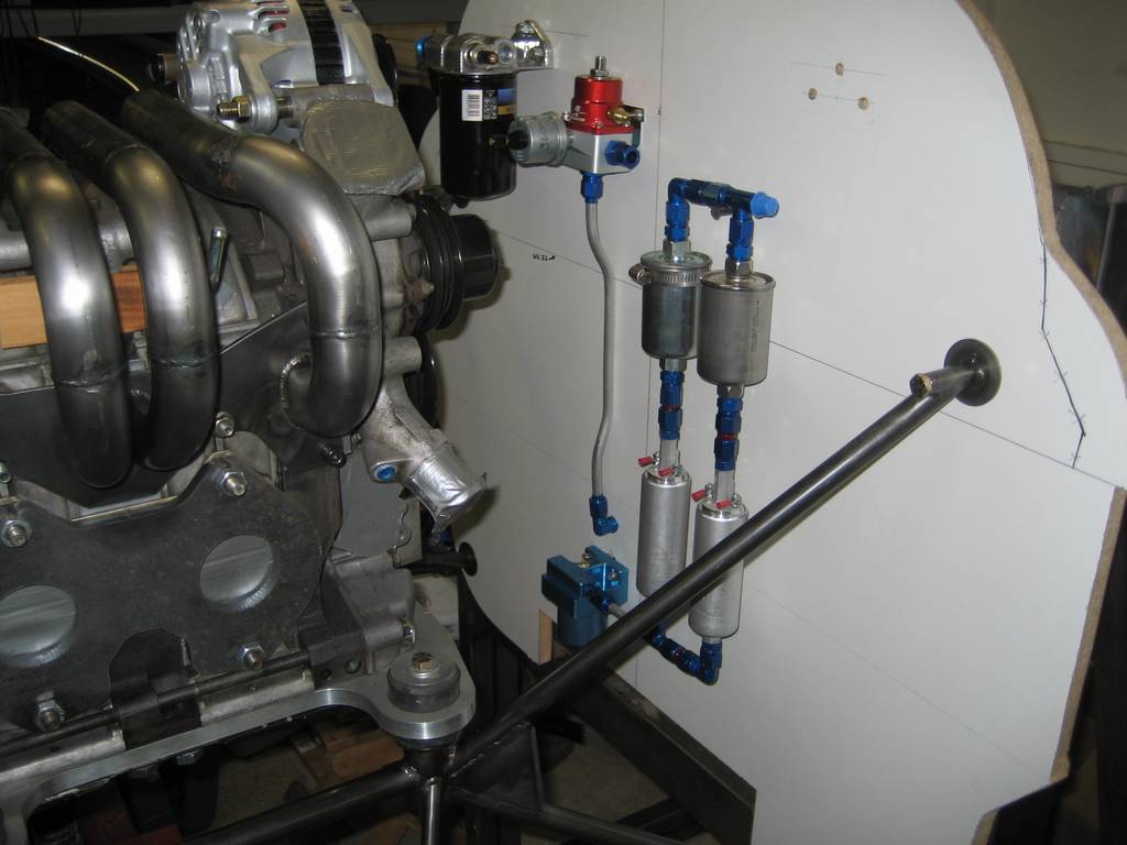
Looking at the firewall, at the top center is the fuel pressure regulator, below that on the right are the two fuel filters, below the fuel filters are the two fuel pumps. At the bottom left, is the remote oil filter and just to the right of it is the gascolator.
-070.jpg "Click for larger view")
In the center of the picture is the remote oil filter. It is very easy to get to in this location. Just to the right of the oil filter is the gascolator.
-075.jpg "Click for larger view")
A view of the firewall from the other side. Top center is the fuel pressure regulator. To right of it are the two fuel filters. Below them are the two fuel pumps. Below the fuel pumps and in the center (the blue object) is the gascolator.
-080.jpg "Click for larger view")
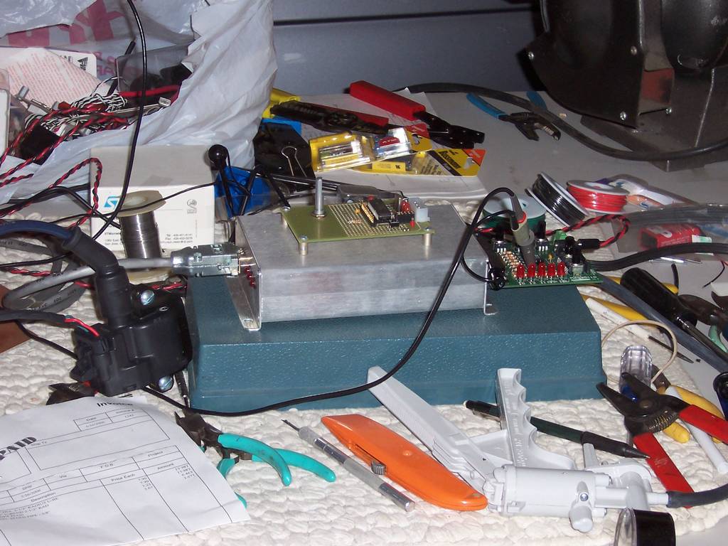
The engine controller is the MegaSquirt version 3.0. This is one expensive puppy.
-090.jpg "Click for larger view")
This is a close up of the other side of the MegaSquirt 3.0.
-100.jpg "Click for larger view")
Above is a MegaSim. This board simulates various sensors on the engine. It allows the MegaSquirt to be optimized without being attached to the engine.
-110.jpg "Click for larger view")
A stack of documentation on the MegaSquirt.
-120.jpg "Click for larger view")
Above is a control panel we put together to run the engine on the stand. We wanted to fully test the engine before installing it on the plane.
-130.jpg "Click for larger view")
This is the back of the control panel.
-140.jpg "Click for larger view")
We kept most of the accessories we removed from the engine.
-150.jpg "Click for larger view")
More accessories we removed

Some more items we removed from the stock engine.
Below is the original webpage made as we progressed on this project
Converting the Mazda 13B Automobile Engine for Use in an Aircraft
Quick links within this page:
Building the test frame
The Engine
Fuel injection and ignition controller
Fuel System
Pictures of the engine on the test stand as of June 2008
Air Plenum - June 15, 2009 Update
Air Plenum - August 2009 update
Overview
This web page will detail the designing, building and testing the conversion of a Mazda 13B automotive engine for aircraft use. It is hoped enough information will be provided to allow others to learn and to duplicate our conversion.
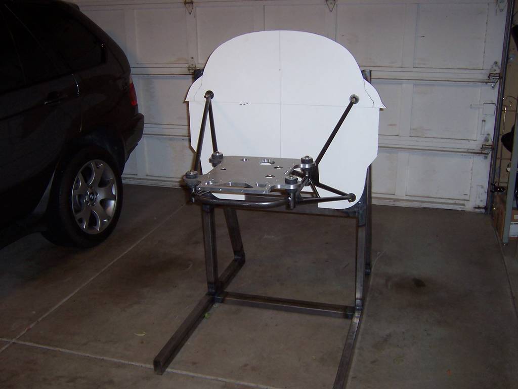
Building the test frame
One of the goals of this project was to have a reliable engine. To do this we felt it was necessary to debug the engine systems before installation. This means running it on the ground until we are confident it will be reliable in the air. We also wanted to run it in an environment as close to the actual installation as possible and transfer most of these tested components directly to the plane. So, a frame was built to run the engine on the ground.
The frame has a full scale firewall mounted to it and the actual engine mount which will be used on the aircraft. The frame has also been designed to be mounted on a trailer so it can be towed to an area suitable for running the engine. We would like to remain welcome in the neighborhood.

|

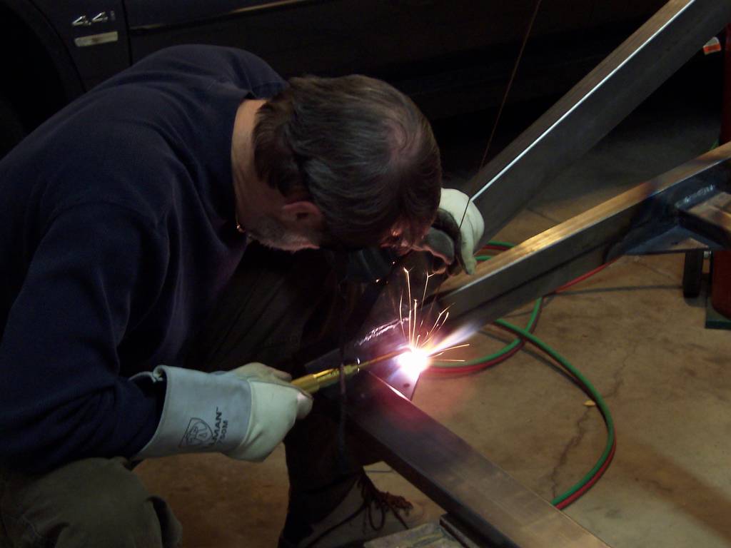
|
| Adjusting the torch. | Welding the frame |
|
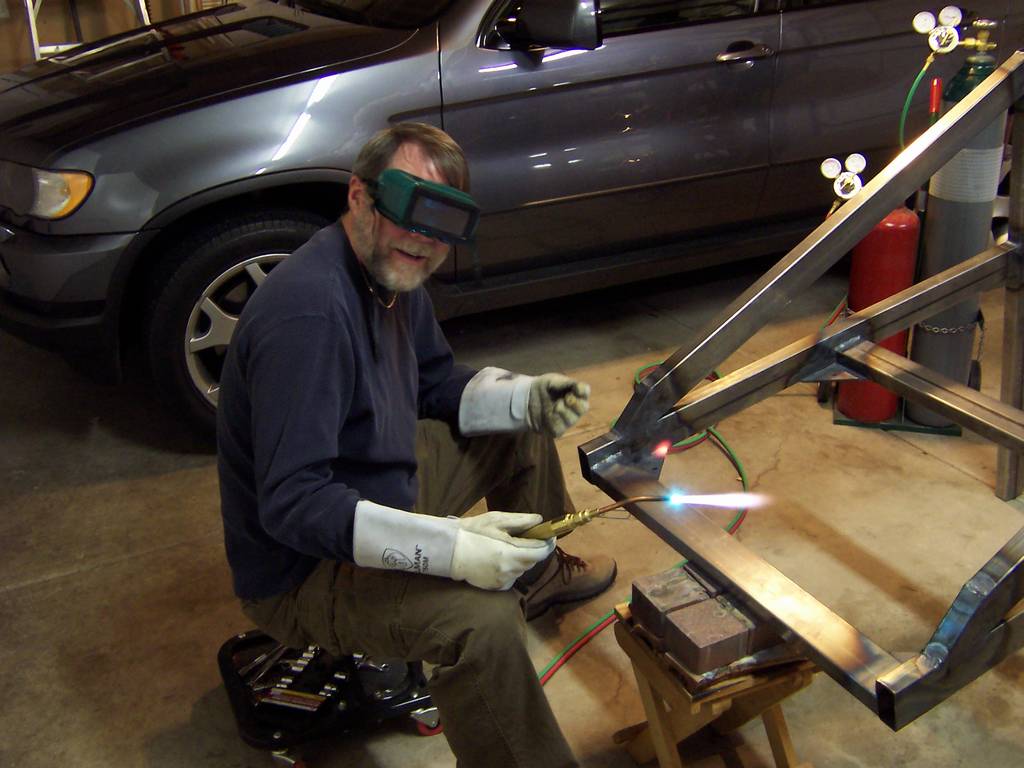
|
| More welding | Smile! |
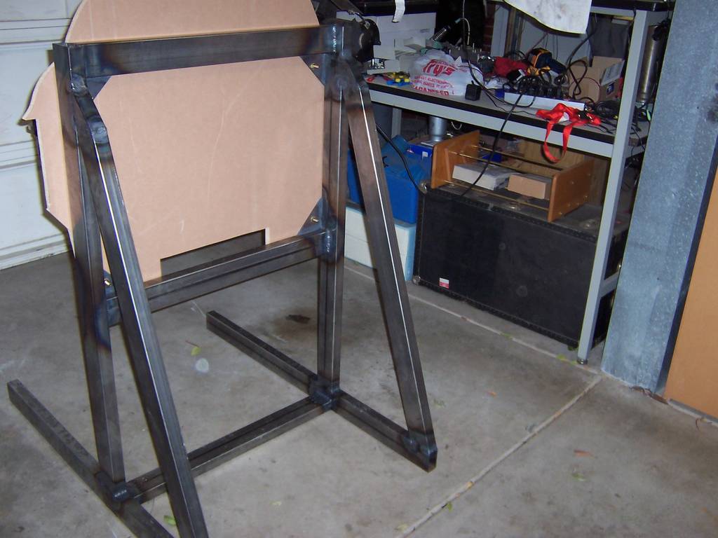
|
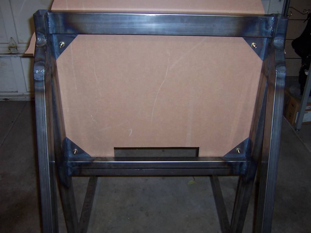
|
| The completed frame | Close-up of the completed frame |
|
|
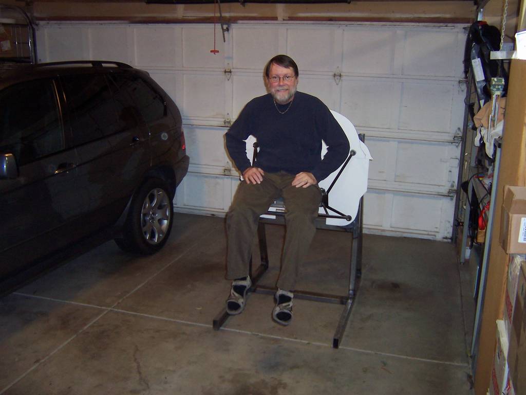
| Engine mount attached to the front of the frame | Testing the weight capability of the frame and engine mount. Yep, it's strong! |
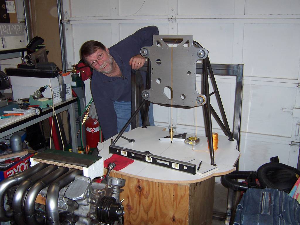
|
| Verifying the center of thrust is where we think it should be. |
The Engine
The engine is a 1989, Mazda 13B Turbo II. It was purchased from a mechanic who had planned on installing it in his car. After having the engine for awhile, life became to busy for him to complete the project, so, he sold it to me. Yea!!!

|

|
| Checking the exhaust manifold for interference with the intake manifold. | Note the custom made fuel/air intake pipes. They are considerably lighter and much smaller than the stock intake. |

|
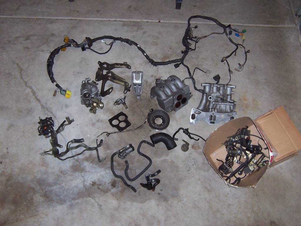
|
| The green box at the top of the engine is a mock-up of the fuel/air plenum. | This is all of the stock components removed from the engine. They are no longer needed. |

|
|
| We put all of the removed stock components on a scale. The weight was 40 pounds! |
Fuel injection and ignition controller
The MegaSquirt will be used as an engine controller for performing the initial testing of the engine. For the final testing and installation in the plane, we'll be using Real World Solutions, Inc rotary EC2 EFI & Ignition Controller.
|
|
| The MegaSquirt on the bench ready for testing. The white vacuum pump in the lower half of the picture is used to simulate the intake manifold vacuum created by a running engine. |
Fuel System
The Cozy fuel system was designed around a carbureted engine. Our engine is fuel injected so a few modifications were needed.
The fuel system for a carbureted engine, is very simple. The fuel flows from the tank to the engine. There is no return feed. In a fuel injected engine, the fuel flows from the fuel tank to engine. Then the fuel which is not used is returned to the fuel tank.
There are many methods to return the fuel. Most require the pilot to keep track of the tank being used and where the fuel is being returned. To simplify the pilots workload, we are returning the fuel to the same tank from which it came. This is done using a fuel valve which can handle both the fuel to the engine and fuel being returned.
A fuel injected engine also requires a higher fuel pressure. In our design, we have two high-pressure fuel pumps. Only one will be needed. The second one is a backup.

|
|
| Schematic of the fuel system. |
| Item | Description | Item | Description | Item | Description |
|---|---|---|---|---|---|
| 1a & 1b |
Fuel Selector Valve | 2 | Sump fitting | 3 | Sump fitting |
| 4 |
Left prefilter | 5 | Right prefilter | 6 | firewall fitting; |
| 7 |
Gascolator | 8 | T fitting | 9 | T fitting |
| 10 |
Primary fuel pump | 11 | Secondary fuel pump | 12 | Primary fuel filter |
| 13 |
Secondary fuel filter | 14 | Flex fuel line | 15 | Fitting |
| 16 |
Fitting | 17 | Pulse dampener | 18 | Primary injector front |
| 19 |
Primary injector rear | 20 | Primary fuel log | 21 | Secondary injector front |
| 22 |
Secondary injector rear | 23 | Secondary fuel log | 24 | Flex fuel line |
| 25 |
fitting | 26 | Fuel pressure regulator | 27 | Fuel pressure sensor |
| 28 |
Firewall fitting | 29 | Manifold pressure line | 30 | Firewall fitting |
| 31 |
Manifold pressure port | 32 | Flex line to ECM |
Pictures of the engine on the test stand as of June 2008
Below are a few pictures taken in June 2008. I'm a bit late getting them posted as it is now September!
At this point, the engine is temporarily mounted on the test stand. The purpose is to see how much room there is for the various items which need to be mounted on the firewall.
The next step is to begin mounting all of the engine accessories. As you can see, the fuel pumps and gascolator have been mounted. We believe they will need to move, but this is our initial location for them.
We are still shooting for a November engine start date. This has been delayed from August due to the 6-month lead time for the Real World Solutions RD-1C 2.85:1 propeller speed reduction unit "PSRU". It is now scheduled to arrive by mid-October. We had placed the order in March, 2008, hoping for a delivery around July.
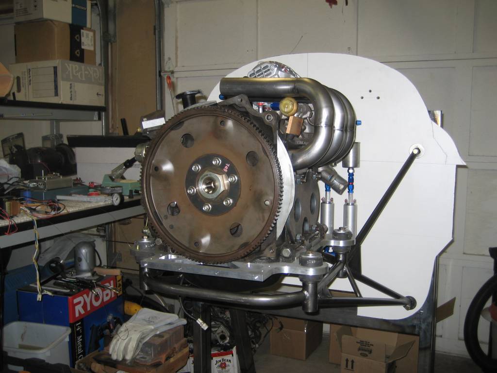
Front view of the engine.
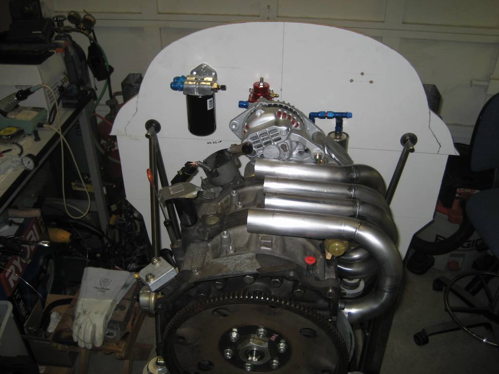
Top view of the engine. The air intake pipes on the top were custom made for us by a local machine shop.
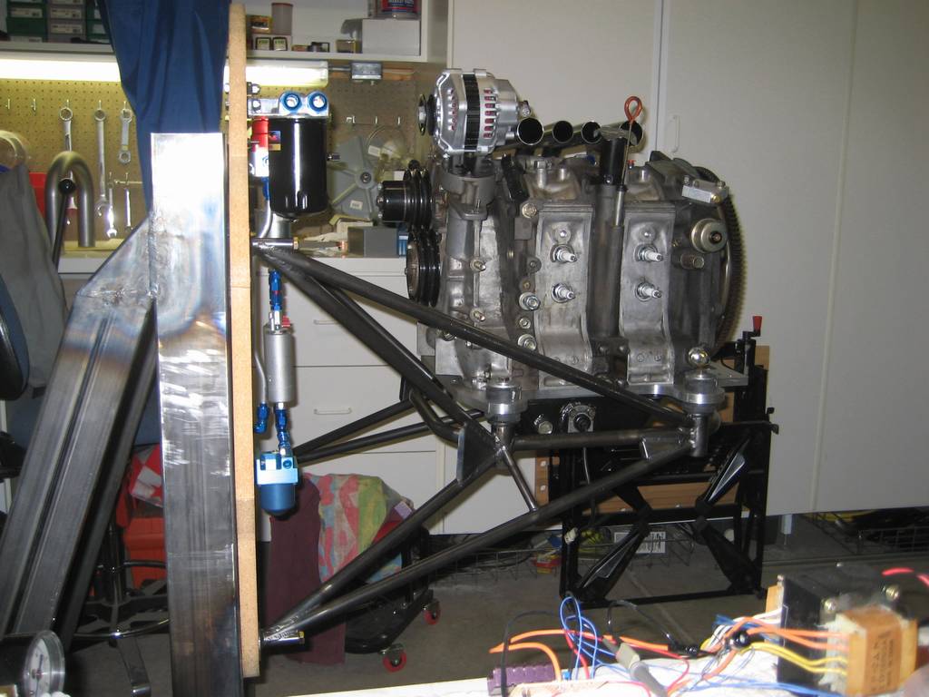
Left side of the engine (as looking toward the front of the plane). The alternator, at the top left of the engine, is a standard 60 Ampere hour alternator. We had it rebuilt and repainted to look new.
The black canister mounted on the firewall is the oil filter.
The red device mounted to the firewall is the fuel pressure regulator and sensor. On the right are two fuel filters (top) and two fuel pumps connected in parallel. At the bottom center of the firewall is the gascolator.
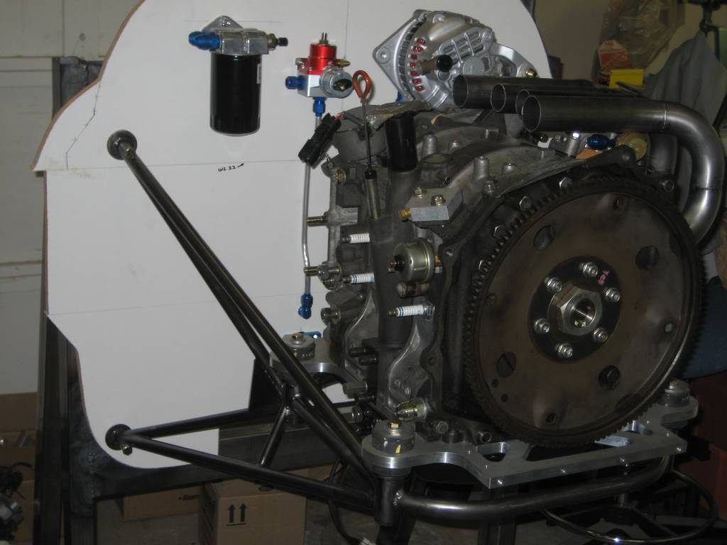
The black canister mounted on the firewall is the oil filter. The flywheel on the engine is the incorrect one. When we received this one from a seller of Mazda engines, we were assured it was the correct one. However, he was mistaken. If you are using the Real World Systems PSRU, it is best to check with them as to which one they require.
Air Plenum - June 15, 2009 Update
The air plenum is where air from the atmostphere or the supercharger is stored until needed by the engine. If the engine is normally aspirated, the pressure in the air plenum will be a couple of pounds above atmosphere. This pressurization is obtained by the ram air being forced into the plenum. In the case of using a supercharger, the air will be pressurized about 4 or 5 pounds above ambient.
When the intake port opens, the air rushes into the engine. Of course, the higher the pressure of the air in the plenum, the higher the quantity of air which will enter the intake port. The more air processed by the engine, the higher the horsepower produced by the engine.
The optimal volume of air for the R13B rotary engine stored in the plenum is more than 2.6 times the volume of the intake chambers. For this rotary, the volume of of the input chamber is 0.75 liters. The volume of the air plenum needs to be greater than 1.95 liters. The plenum we have designed and are building has a capacity of about 3 liters.
The entrance to the air plenum is the throttle body. As the throttle is opened more air will be allowed to flow into the plenum. The more air in the plenum, the more horsepower produced by the engine. Restricting the amount of air allowed to flow into the plenum will reduce the engine speed.
The air plenum is made of fiberglass and foam. The foam used is wing foam, which is low density 2 pounds per ft3 styrofoam. The foam was cut as sheets 1/4 inch thick. The foam was cut using a hotwire saw.

Cardboard mock-up of the air plenum. The hole in the center is where the oil filler pipe and the dip stick are located. The sides of this hole will be enclosed with foam and fiberglass.
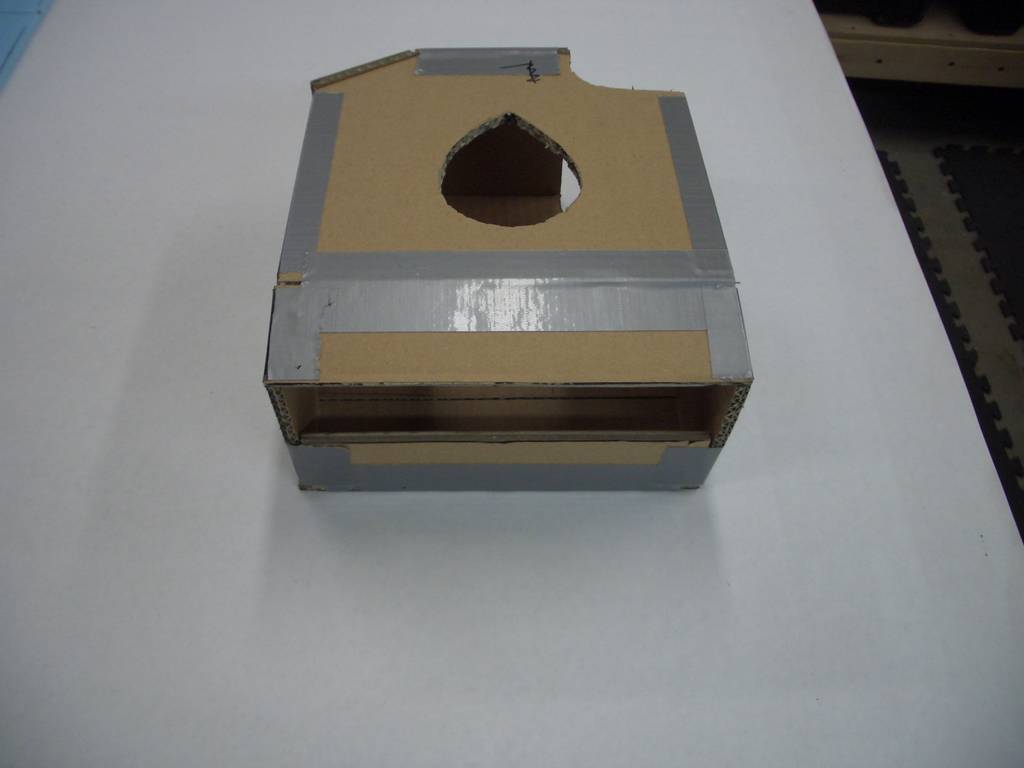
The slot in the forground is where the air intake tubes enter. This will be custom fitted around the tubes.

The notch at the bottom left of this picture is a cut out to provide clearance for a nut on the oil tap for the PSRU.
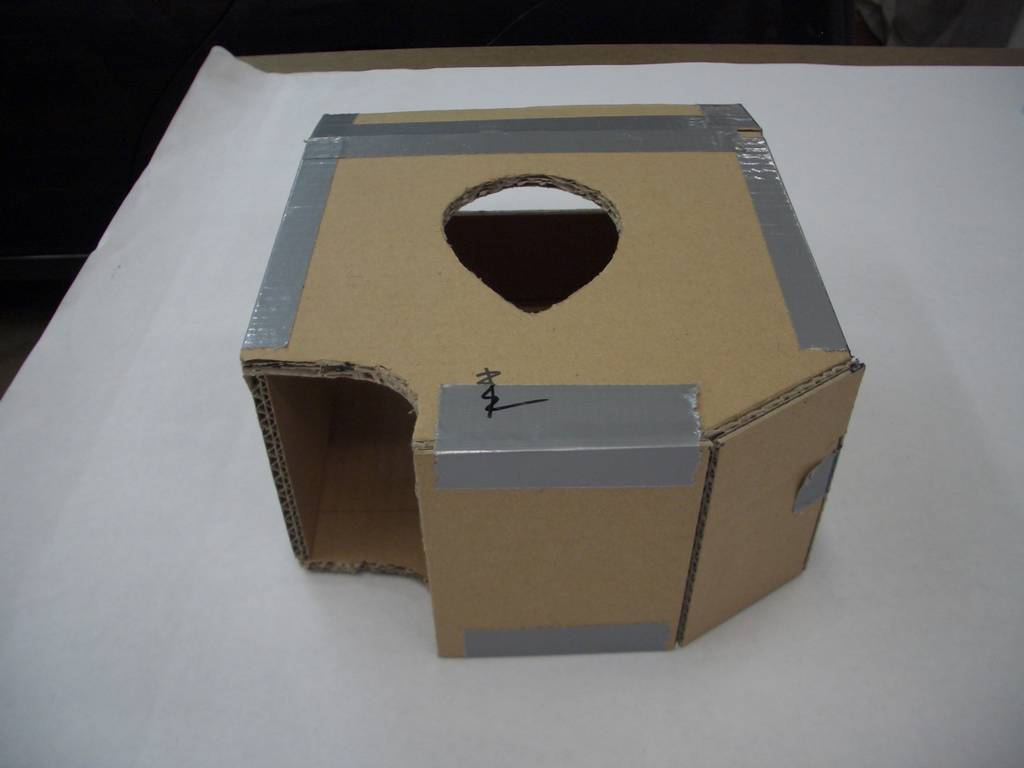
The curved hole in the foreground fits around the distributer. It will be enclosed with foam and fiberglass.
The forward face in this picture is where the throttle body will attach. A large diameter hose will lead from the throttle body to either the RAM air or to the super charger.
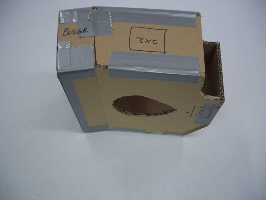
The 2 x 2 inch square shown on the upper side is for a peice of 1/4 inch alumninum. This will be drilled and tapped for the manifold pressure sensor and for a tube which is the manifold pressure input for Tracy Crook's engine controller.
The rectangle near the "point" of the center hole (for the oil filler pipe) is for a 1 x 2 inch piece of 1/4 inch aluminum. This will be used to attach a support bar to the engine. Since the throttle body will be nearby, a support here is essential.
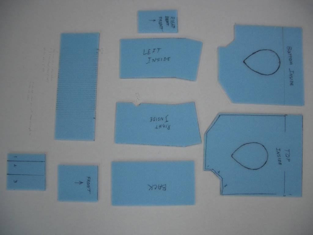
Foam pieces used to make the air plenum
Air Plenum - August 2009 update
We are currently working on the intake air manifold. Our original idea of creating it using fiberglass was scrapped. The reason is the supercharger we are planning on using. We felt the air from the supercharger would be hotter than the Tg, fiberglass temperature transition point. This is the point at which it will soften and deform.
Our current plan is to make the air plenum out of very thin steel. This will be a little heavier, but not much. Steel will not have the temperature sensitivity that fiberglass has.

Tracy Crook PSRU mounted on the engine

Tracy Crook PSRU mounted on the engine

Fuel pumps mounted and in the lower right corner is a bracket for the electrical connector from the engine control unit.

Work bench used to develop the test engine control unit. Note the temporary mounting of the spark plugs on the bottom center. This is for testing the MegaSquirt engine control unit.