Page updated on: March 5, 2013
August 1, 2013
December 12, 2013
June 6, 2014
December 8, 2014
June 1, 2015
Chapter 18 - Turtleback and Canopy
Quick links within this page:
Step 1 - Building the Turtleback Form
Step 2 - Construction of Turtleback and Inside Layup
Step 3 - Turtleback Bulkhead and Rib
Step 4 - Contouring and Glassing Outside of Turtleback
Step 5 - Installing the Windows
Step 6 - Installing Hinges on Longerons
Step 7 - Installing Upper Half of Firewall
Step 8 - Installing the Turtleback
Step 9 - Engine Mount Reinforcements
Step 10 - Installing the Canopy
Step 11 - Building the Canopy Frame
Step 12 - Carving the inside foam
Step 13 - Laying Up Canopy Hardware Reinforcements and the Inside Skin
Step 14 - Provision for Removable Fuselage Top
Step 15 - Installing Canopy Hinges, Cutting Out Frame and Installing Drip Rail
Step 16 - Installing Fuselage Top
Step 17 - Canopy Lip and Instrument Cover
Step 18 - Installing Access Door
Step 19 - Installation of Canopy Latches
Step 20 - Safety Catch
Step 21 - Canopy Handle
Step 22 - Canopy Stop
Step 23 - Cockpit Ventilation
Chapter Overview
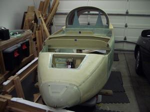
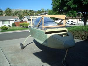
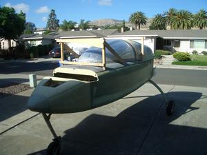
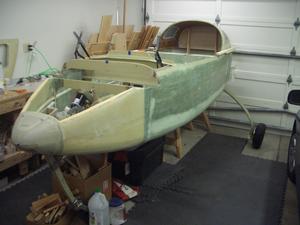
WoW! We are making good progress on the airplane. So far the fuselage looks like a boat. Hang in there for one more chapter and it will start looking more like an airplane.
In this chapter I will build a form for the turtleback, build the turtleback and bulkheads, install windows in the turtleback, fit the canopy, build the canopy frame and fuselage top forward to bulkhead F28, and install the hinges, latches, locks and cockpit vents.
Before installing the turtleback permanently and building the canopy frame, it is recommended that the wings (Chapter 19), jig the wings to the centerspar, and permanently install the centerspar be completed.
An excellent quality, formed plexiglass canopy and molded side windows are available through the recommended distributor. The canopy is free blown into a 3-dimensional mold to match the turtleback and fuselage contours, while maintaining excellent optical quality. The side windows are drape molded to match the curvature of the turtleback. Canopy hardware is available prefab from the recommended distributor.
One modification I am making to the plans is to have a Forward Hinged Canopy (FHC). The primary reason is to avert possible problems with the canopy opening in flight. The plans method of having a side hinged canopy has been the cause of several crashes due to the canopy popping open during take off. The plane will still fly without problems, however, many pilots are distracted by the canopy suddenly opening and they forget to "fly the plane", resulting in a crash.
A secondary reason is it will allow passengers to enter the plane from either side. Granted, this is not a big deal, just a small convenience.
Step 1 - Building the Turtleback Form
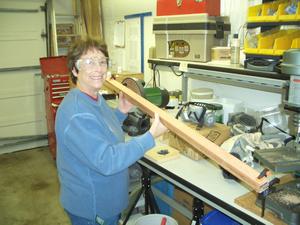
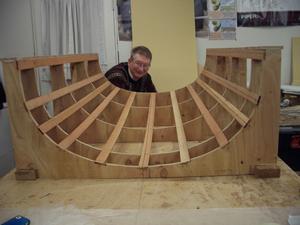
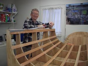
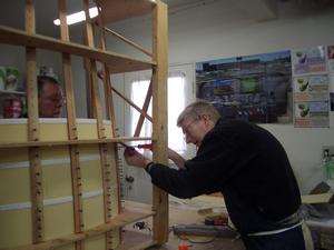
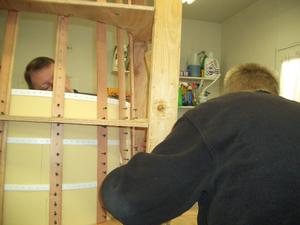
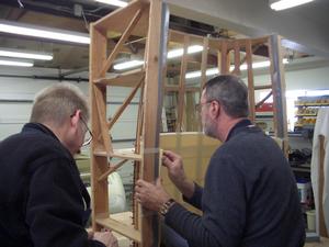
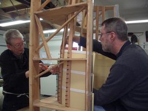
Building the form was a lot of fun. I even had my girlfriend, Helen, helping me out. She really enjoyed it also.
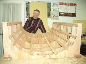
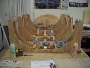
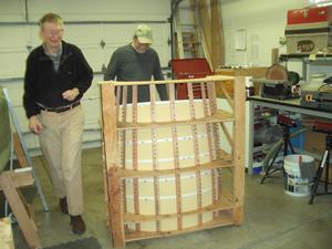
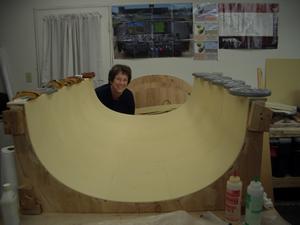
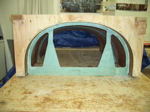
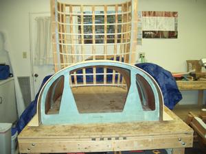
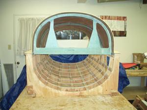
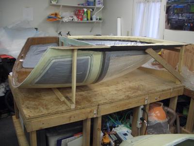
All the stringers are now in place and the jig is ready for building the turtleback.
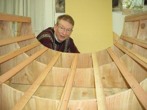
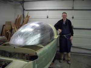
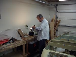
I don't work when wearing a nice sweater. This picture was taken as I was heading out for a Christmas dinner party. I had a few minutes before it was time to leave and I had realized I didn't have any pictures of the completed jig.
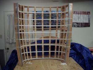
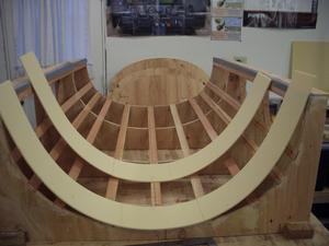
NOTE: this picture was taken after the turtleback was built. The plastic strips are added to the jig when the foam is placed in it.
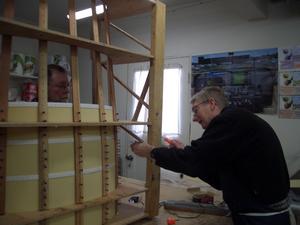
Once the glue has cured, the jig is very sturdy and can be moved around. This is a real convenince as it can positioned high for easy placement of the foam and lowered onto some saw horses for easy application of the fiberglass.
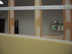
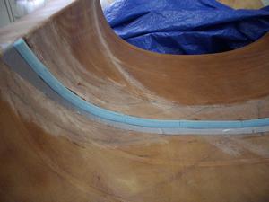
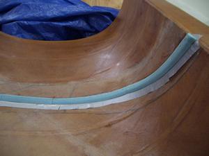
The white strips are plastic "hangers" for plumbing. The plans say to use thin strips of aluminum to keep the edges of the foam butted against each other. I didn't want to spend the money to purchase the aluminum to make the strips. I found these plastic plumbing hangers in a roll of 25 feet, it took two rolls.
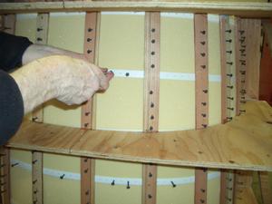
The plastic hangers worked well and were cheap. They cost about $2 per roll. They are 3/4 inch wide and have holes down the center. I used the holes for drywall screws to hold the edges of the foam in close contact with the strip.
Step 2 - Construction of Turtleback and Inside Layup
And now the fun begins! In this step, the foam is placed into the jig and the inside fiberglass is applied.
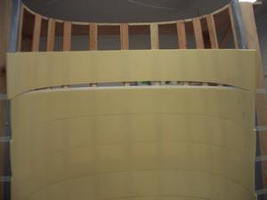
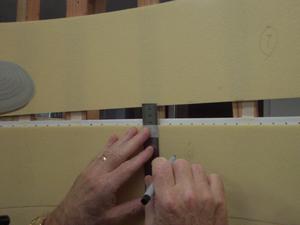
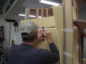
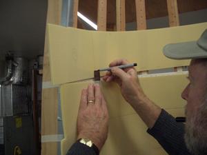
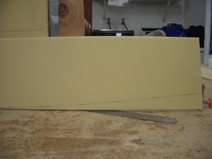
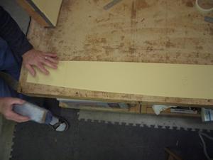
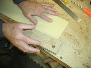
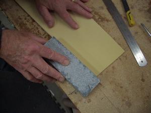
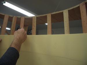
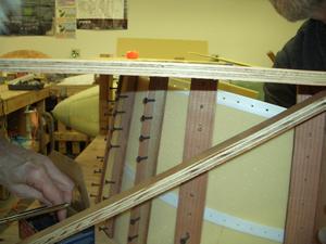
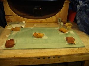
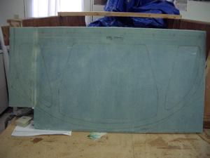
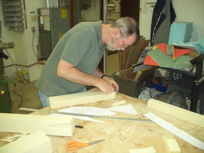
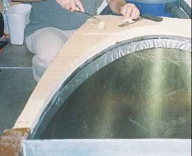
The next few steps show how the foam was trimmed. All the foam strips were intially cut the same width, according to the plans. Then the foam was put into place. Notice that there is a big gap in the center between the two pieces of foam.
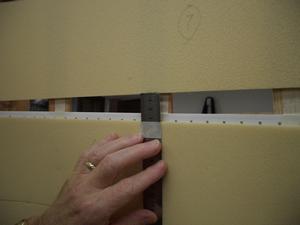
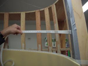
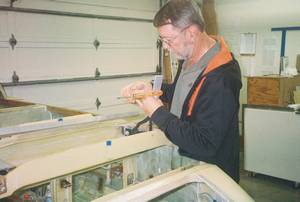
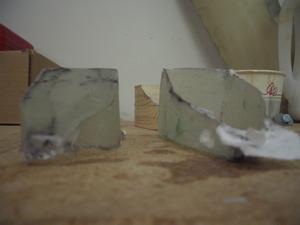
The gap in the foam was measured at the widest location. This is not the widest location in this picture. A piece of tape was placed on the ruler to mark the widest gap. In this picture, this strip appears to be about 3.3 or 3.4 cm wide.
Yes, I prefer to use the metric system when I have to make measurements. I find the metric system much easier to use. For me, it is a pain when having to deal with fractions, like 1/16, 1/8, etc. However, if I am transfering marked measurements from the plans, I use the English system as I don't want to take a chance of making a conversion error.
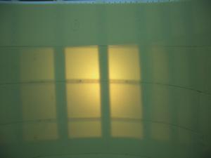
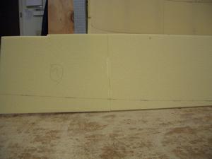
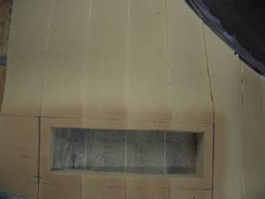
With a light shining from the back, you can see how closely the foam fits. There is very little gap. It is not perfect, but close enough. BTW, no additional sanding was done after the initial sanding to the line had been completed.
Using this method is easy and does not require a trial and error method of fitting the pieces into place.
I found this method of cutting the foam on Rick Maddy's website. It worked very well and I'm grateful to him for documenting it.
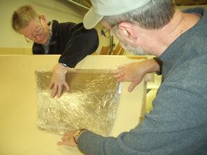
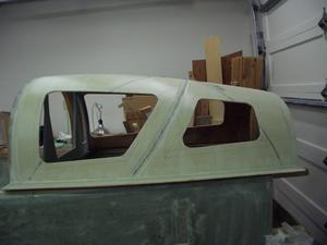
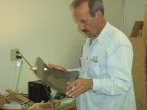
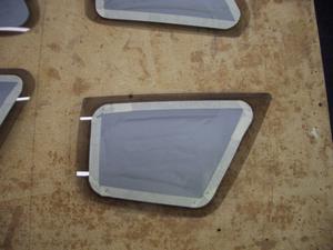
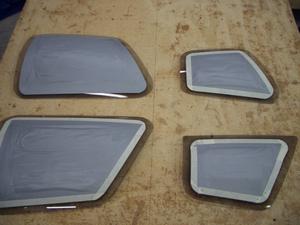
Checking the curvature of the side windows with the side of the turtle. They didn't match, however the windows are flexible enough they'll conform to the shape of the turtleback.
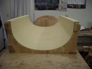
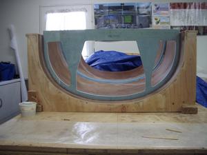
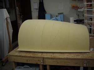
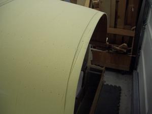
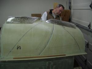
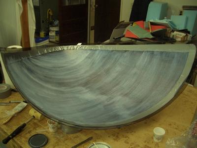
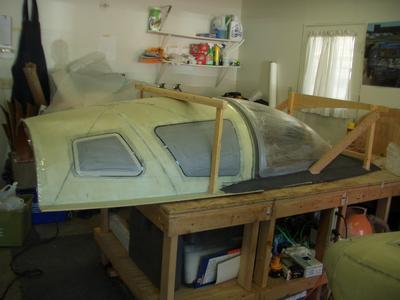
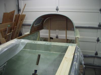
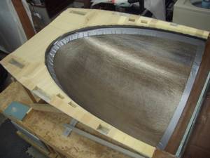
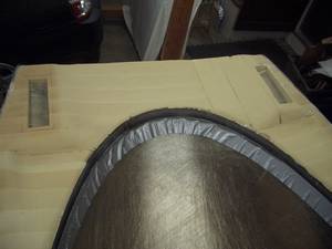
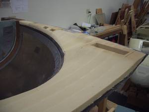
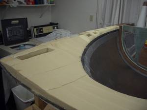
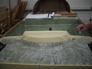
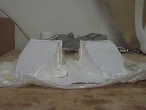
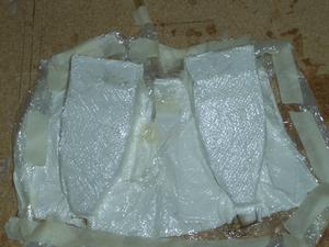
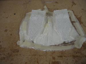
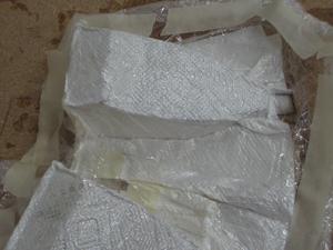
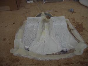
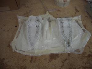
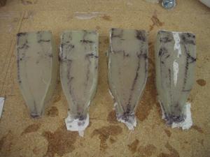
This is a view of the completed turtleback, ready for fiberglassing. Masking tape has been placed over the seam between each piece of foam. As you can see, the tape has lifted from the foam. I *thought* it would lay down correctly once it was wetted out with epoxy, but I was wrong. If I had it to do again, I would have filled the gaps between the pieces of foam with string to prevent the epoxy from leaking through to the other side when the fiberglass was applied.
I don't have any pictures of the completed inside layup. However, pictures of the rest of the steps show the completed layup.
Step 3 - Turtleback Bulkhead and Rib
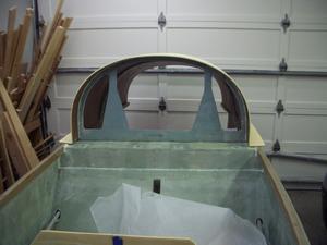
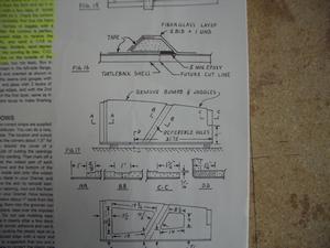
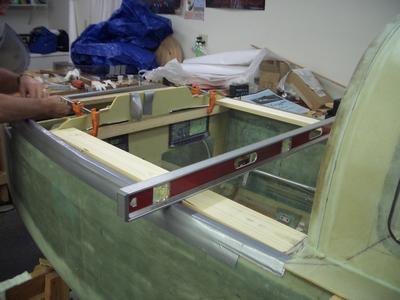
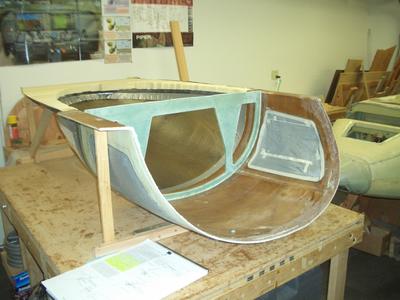
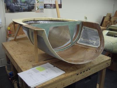
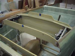
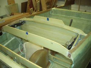
In this step, the bulkhead between the front seats and the back seats is built. The drip rail along the future cut line that separates the movable part of the turtleback from the fixed part, is also built.
Step 4 - Contouring and Glassing Outside of Turtleback
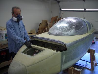
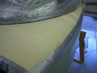
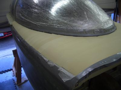
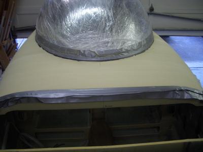
The outside of the turtleback is sanded smooth to remove any ridges where two pieces of foam meet. Depressions are added where there will be overlapping fiberglass to the canopy, to the firewall and for the drip rail. Once the preparation work is completed, two layers of UNI are applied to the outside.
Step 5 - Installing the Windows
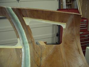
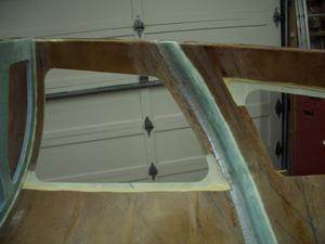
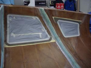
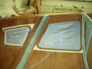
The holes for the side windows are cut in the turtleback. Then the windows are cut to size and installed. Finally, the opening needed to install each window is fiberglassed closed.
Step 6 - Installing Hinges on Longerons
In this step, the plans hinges on the longerons are installed. Since I am building a front hinge canopy (FHC), the hinges will be on the front. See step 15 for details on the installation of the hinges.
Step 7 - Installing Upper Half of Firewall
This was a real fast step of floxing the firewall to the longerons. The key elements were to ensure the upper firewall was square to the fuselage centerline and that it was perfectly parallel with the bottom firewall.
Step 8 - Installing the Turtleback
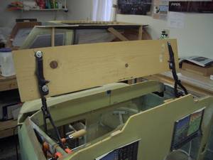
This step has been deferred as I wanted to have easy access to the back seat area. To make sure everything lines up, I drilled four 1/4 inch holes in the turtleback (only the portion that gets permamently attached to the longerons). Then I placed four AN4 bolts into these holes to keep the after portion of the turtleback in place.
Step 9 - Engine Mount Reinforcements
Since the spar has not been installed, I'm deferring this step till after the spar is installed.
Step 10 - Installing the Canopy
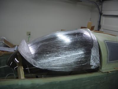
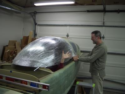
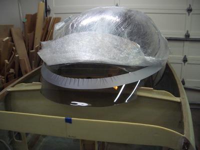
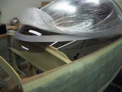
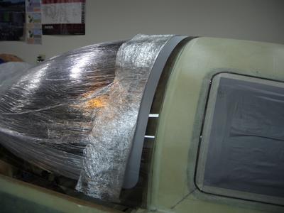
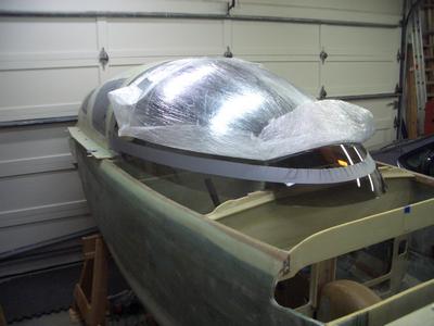
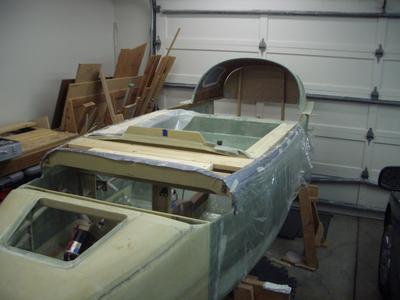
In this step, the canopy is fitted to the fuselage and prepared for the placing of the frame around it.
I am planning on having a Front Hinge Canopy (FHC), so I am following both the Cozy IV plans and the European Cosy Classic plans (basically a Cozy III) by Uli Walters, making adjustments as necessary to accomodate the FHC.
Uli had designed a FHC into his Cosy Classic plans and is making chapter 18 available so others can duplicate his design. In 2006, he was selling the FHC plans for $50.
Step 11 - Building the Canopy Frame
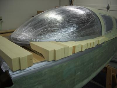
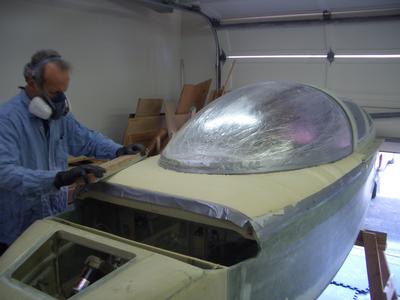
In this step, the canopy frame will be built. The canopy frame is the portion of the fuselage which extends from the canopy to the fuselage sides. The canopy frame is made of urethane foam, which can be sanded to shape very easily.
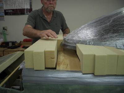
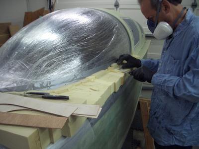
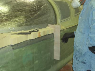
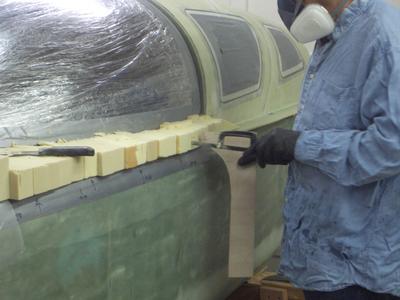
The frame is made up of many small blocks of foam. These blocks extend under the canopy and over the longerons (upper side of the fuselage). Each block is about 2 inches wide and there are about 24 of them on each side.
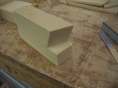
While making the frame, I came up with an easy way to get each block to fit around the canopy. I will out line the steps below.
Since I am modifying the canopy to be a Front Hinged Canopy (FHC), my first deviations from the plans will occur on this step. The plans call for a layup schedule of:
| Number of layers | Fiberglass Type | Fiberglass orientation |
|---|---|---|
| 2 | BID | 45 degrees |
| 2 | UNI | Fore and aft |
For the front hinge canopy (FHC), Uli Walter's Cozy Classic plans have two additional layers of carbon fiber BID. This is to stiffen the canopy since all the weight will be on the two hinge points at the front of the canopy. The side opening canopy has the weight distributed along the side of the canopy. Here is the layup which Uli specifies:
| Number of layers | Fiberglass Type | Fiberglass orientation |
|---|---|---|
| 2 | BID | 45 degrees |
| 2 | Carbon Fiber BID | 45 degrees |
| 2 | UNI | Fore and aft |
Uli Walter specifies the carbon fiber to be Interglas 98151 or similar. Interglas is a European (German) company and I could not find a US distributor for their products. I then searched for a US based company that sold a similar product. Here is a comparison of what I found:
| Brand Model |
Weave | Yarn Type | Thread Count threads/inch |
Weight oz/yd2 |
||
|---|---|---|---|---|---|---|
| warp | fill | warp | fill | |||
| Interglas 98151 (Uli's recommendation) |
twill 2x2 | 3K | 3K | 15.2 | 15.2 | 7.23 |
| Soller Composites 2x2TW #2 |
twill 2x2 | 3K | 3K | 12.5 | 12.5 | 5.9 |
| Soller Composites 2x2TW #3 |
twill 2x2 | 3K | 3K | 17 | 17 | 8 |
I chose to use the Soller Composites 2x2TW #3. I felt it was better to substitute a stronger fabric than the original.
I calculated I would need about 7.5 yards of 50" wide carbon fiber. Since the 2013 price was around $34 per yard plus shipping, I didn't want to buy too much. However, I also didn't want to have to order additional carbon fiber if I should run out. I chose to buy 10 yards. At these prices, the cost was almost as much as the canopy itself!
As I write this, I have fiberglassed the top of the canopy frame. I have not yet fiberglassed the inside, so I don't know how close my estimate on the amount of carbon fiber needed was. I'll try to remember to update this section when I have completed the bottom (inside) part of the canopy frame.
Update: I have finished fiberglassing the canopy and I used a total of 5 yards of 50" wide carbon fiber. I guess I over-estimated the amount I needed. If I were building another canopy, I'd purchase 6 yards of the 50" wide carbon fiber.
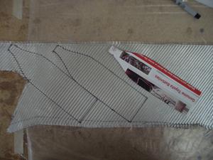
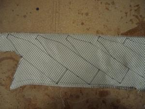
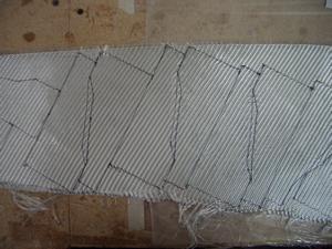
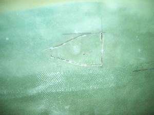
I'm very careful in my use of fiberglass. For large layups (and many small ones) I make a paper template. For the larger layups, it usually takes several modifications to the original template before I have the shape I want. I then use the template to cut out the fiberglass. This technique significantly reduces the amount of waste I end up with.
One note, when I ordered the product, they offered to fold the carbon fiber to get a better shipping rate. I refused and requested it be sent to me on a roll. The reason is carbon fiber can be damaged if it is creased and I didn't want to take a chance on damaging it.
During my research of carbon fiber, I came across Elite Carbon Fabric's website which had a description of various fabric weaves and the definition of common terms used with carbon fiber products. If their website no longer exists, here is a PDF copy of the information.
I hope the above information will help you to find a suitable carbon fiber for your canopy frame.
Step 11 Pictures
Step-by-step Method of Carving the Foam Blocks
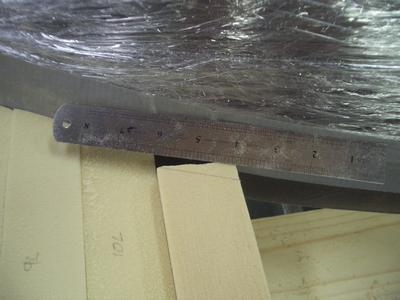
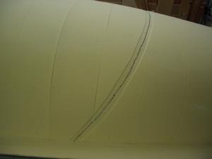
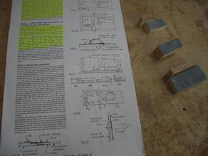
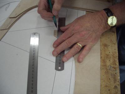
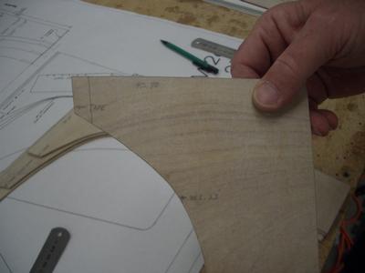
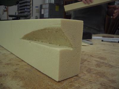
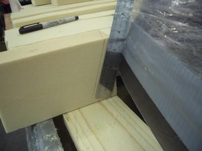
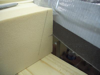
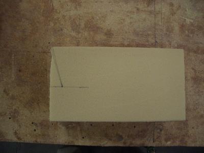
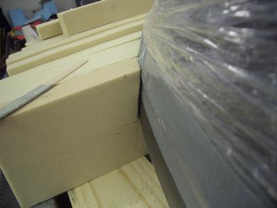
My step-by-step method of shaping the blocks to fit around the canopy. The first step is to place the block against the canopy. Then place a straight edge against the canopy and draw a line on the block. This gives a horizontal reference as to the angle the block needs to be cut to fit against the canopy.
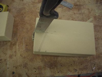
The reference line is then moved so it goes from the corner furthest from the canopy (left side in this photo) to the right side. I'll call the intersection of this line with the right edge of the block, point "A". The distance of point "A" from the canopy is determined by the reference line.
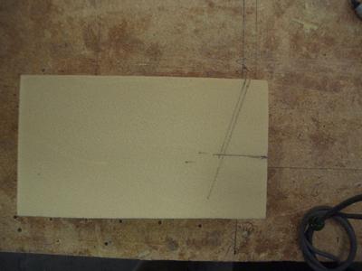
The block was then taken over to the bench to construct the remaining lines.
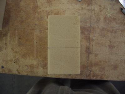
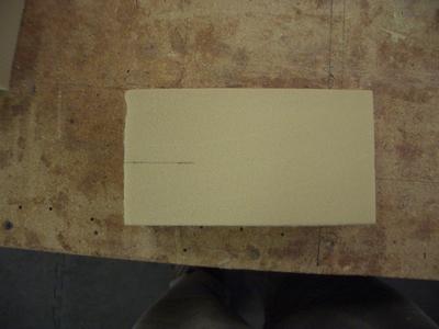
The next line to be constructed extends from the top of the block at point "A". The vertical line is drawn parallel to the vertical reference line. Note that it appears to be only about 1/16 inch from the reference line (the reference line is the one that is a lot longer than the constructed line).
The next line to be constructed is made by extending the mark for the bottom edge of the canopy to the line just constructed. This line is parallel to the bottom edge of the block.
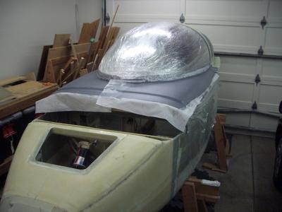
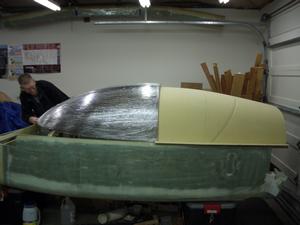
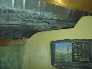
The fiberglass layup has been completed. The dark color is due to the use of carbon fiber for strength. The layup schedule was, 2-layers of BID at 45 degrees, then 2-layers of carbon fiber at 45 degrees and finally 2-layers of UNI oriented fore to aft. Each each layer is made up of two pieces that are overlapped and staggered at the front of the canopy. As a top layer, I added peel ply.
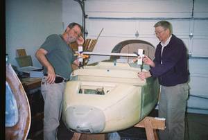
When we build up the hinge mounting pads on the canopy frame, we would like for them to cure as flat and as parallel to each other as possible. To achieve this, Jeff came up with the idea of taking the aluminium mounting plates and epoxying them to a square metal tube. When we build the hard points, this jig will be put in place with weights on top to force the pads to be parallel. Of course we'll put plastic or wax paper between the plates and the pads so they won't be permanently attached.
Step 12 - Carving the inside foam
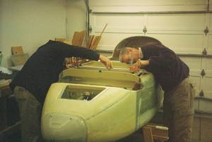
In this step, the foam on the inside of the canopy frame is sanded to shape. Since I am not very good at shaping foam, Jeff volunteered to do it.
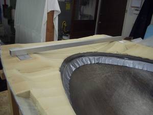
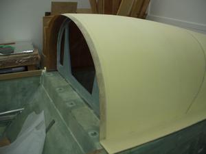
This is what it looks like after shaping. Note the hinge mounting points for the forward opening canopy. We left the foam at it's original height, even with the longerons, in the areas adjacent to where the hinges will be attached to the canopy.
The square tube with the aluminium mounting pads attached is just sitting in the holes for the hinge hard points.
Step 13 - Laying Up Canopy Hardware Reinforcements and the Inside Skin
The hard points are made by layering flox and BID. The flox layers were 2 to 3 mm thick (approximately 0.1 inches). Around 12 to 15 plys of BID were used for each hard point.
The hard points made were:
- Two mid hard points for the middle latches (one on each side)
- Two forward hard points for the forward latches (one on each side)
- Four hard points for the canopy pull down handles (two on each side)
- Two hard points for the hinges (one on each side)
The inside skin layup schedule for the inside is the same as for the outside of the canopy frame. It was:
- Two layers of BID
- Two layers of carbon fiber BID
- Two layers of UNI
Step 14 - Provision for Removable Fuselage Top
Details of step will go here
Step 15 - Installing Canopy Hinges, Cutting Out Frame and Installing Drip Rail
Now for the meat of the Front Hinge Canopy "FHC". There have been several designs for a FHC. Uli Walter's design is the one most people use. It is fairly simple using two aluminium hinges attached to F28. This puts stress on F28 and it needs to be strengthened to support the weight of the canopy.
A few years ago, while attending the annual Canards West Fly-in, I met Stuart and his brother who are both Cozy builders (separate projects). Stuart's idea was to use an automotive trunk hinge for a Front Hinged Canopy "FHC". These could be mounted on the longerons which is already strong enough to support the canopy. Also most of these hinges already have a built-in gas spring, so there was no need for the long gas spring Uli used. I immediately liked the idea and set about to see what could be designed.
To contact Stuart for more information on his implementation, you may EMAIL him at:
![]() Note: This is an image, so you'll have to type his EMAIL address in manually. Copy and paste will not work.
Note: This is an image, so you'll have to type his EMAIL address in manually. Copy and paste will not work.
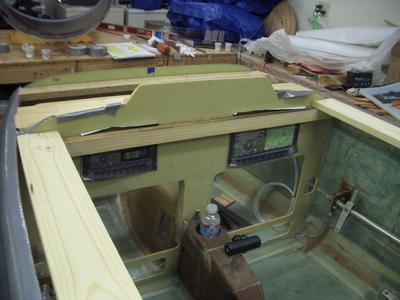
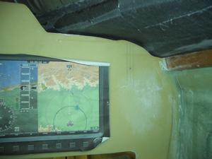
The main disadvantage of using the automotive trunk hinge is that it takes up a fair amount of room along the longeron which may interfere with the avionics on the instrument panel. In my case, I don't think there will be much interference as the hinges are in a location just above the fresh air vent, which takes up a lot of room.
The advantages are:
- Attachment points are anchored to the longeron
- Spaced wider apart than Uli's hinges, therefore provides more stability
- Much more sturdy than the aluminium hinges
- A proven technology used by the automotive industry
I found a pair of BMW trunk hinges on eBay. They cost about $20 for the pair. Stuart used Audi trunk hinges on his project. I believe he also purchased his from eBay.
Here is a list of parts I purchased for the front hinge canopy:
- Left and right BMW trunk hinges, part number OEM BMW E46 99-06 325i 330i M3; Trunk Hinges Pair Left/Right BLACK. I purchased them used on eBay for $20.00 for the pair.
- Two gas springs: BMW SKU: 5123 8 402 551; Model #: 3466PL 0640N 04902 B 27; However, a cheaper clone is available.
It is made by SACHS and the model number is SG402031; I purchased them from
Rock Auto.
In 2013, I paid $14 each for the gas springs, compared to over $150 each for the BMW gas springs. The key parameters of this gas spring are:
- Force: 640 N (about 140 pounds).
- Extended length: 290 mm.
- Compressed length: 193 mm.
- Diameter of gas reservoir: 19 mm.
- Diameter of extendable shaft: 8 mm.
- Travel length: 96 mm.
- Two pieces of the Ball Mounting Hardware: McMaster Carr. If link is not working, here is the drawing for the part: Ball Mounting Hardware. In 2013, I paid $1.00 each for the ball mounting hardware.
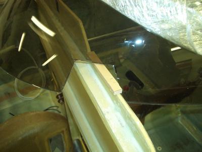
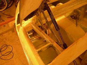
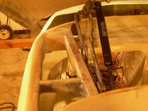
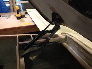
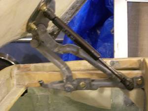
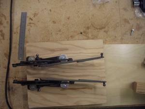
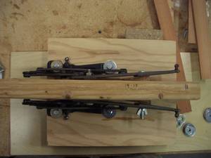
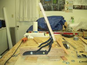
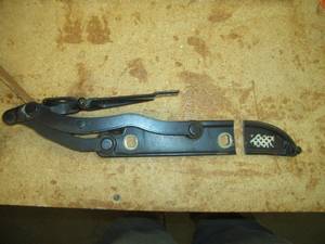
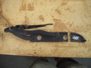
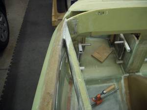
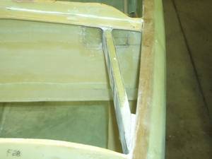
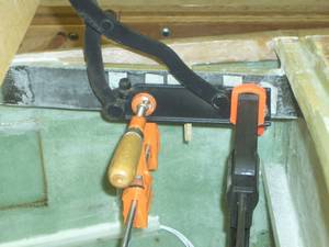
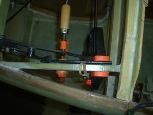
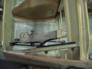
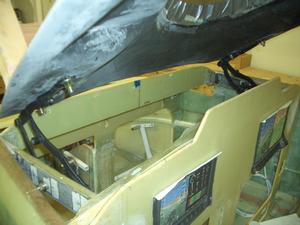
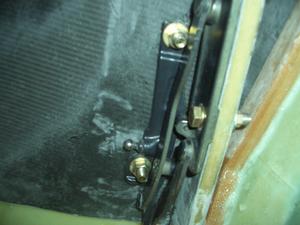
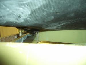
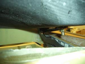
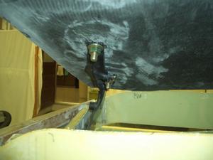
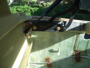
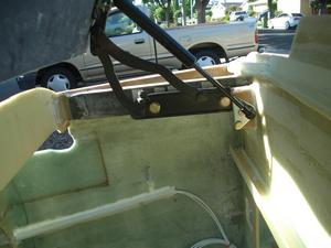
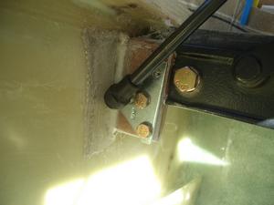
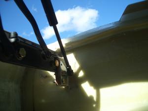
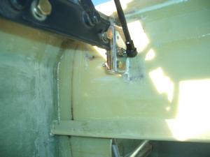
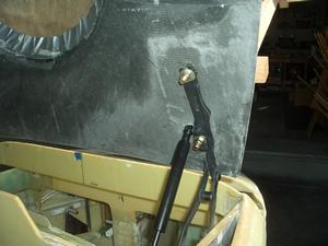
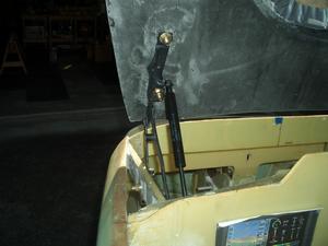
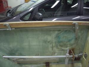
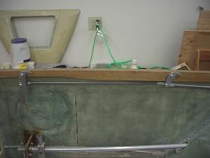
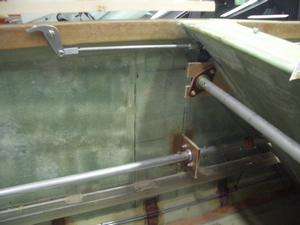
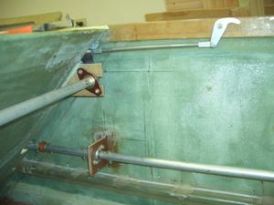
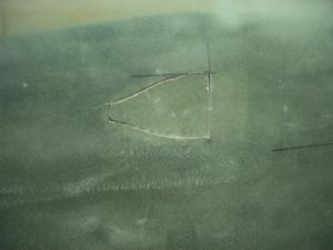
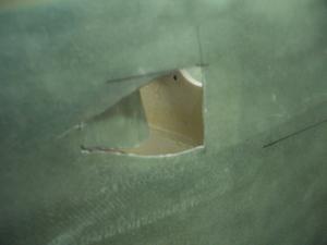
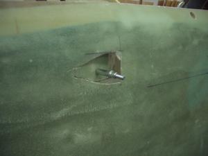
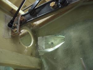
One problem both Stuart and I found and was the length of the hinge was longer than the distance between the instrument panel and F28. I cut the BMW hinges down to fit, as shown in the photos below. Stuart's hinges were a bit shorter than mine and he was able to cut a hole in F28 for the end of the hinge to fit through when the canopy was down. This is something to keep in mind when selecting a hinge to use.
I have included some pictures of Stuart's implementation using Audi trunk hinges for comparison. I hope you find them useful. My implementation continues after Stuart's pictures.
Stuart's Implementation Using Audi Trunk Hinges
End of Stuart's Implementation Using Audi Trunk Hinges
My Implementation Using BMW Trunk Hinges
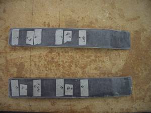
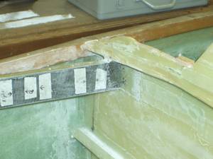
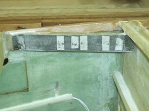
The layup schedule for the mounting bracket was:
- 2-layer of BID, which was put on when the turtleback bulkhead was built
- 2-layers of carbon fiber BID to add stiffness
- 2-layers of UNI oriented fore and aft
This really made the bracket strong. I was impressed with how effective the carbon fiber was.
The adhesive tape on the mounting bracket was used to mark the edges of the hard points and the center line for each of the hard points.
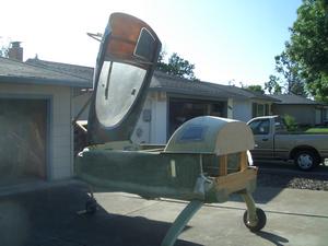
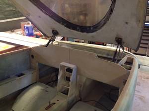
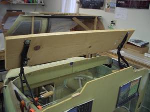
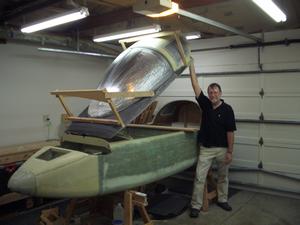
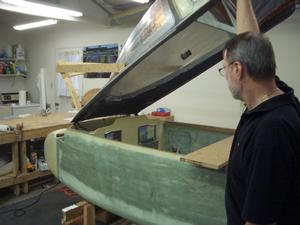
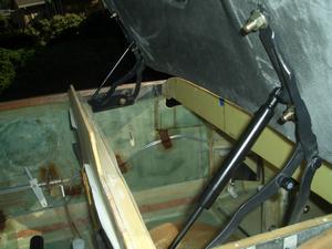
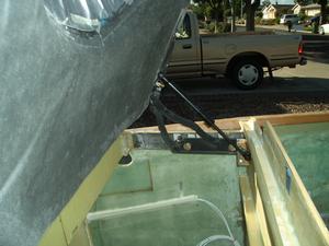
Canopy fully open with the gas springs installed.
The canopy is surprisingly stable in the open position. When moving it from side to side, it is very stable. I don't think their will be any problem in a high cross wind with the canopy open.
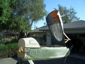
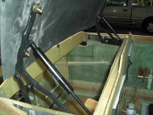
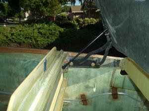
Canopy fully open with the gas springs installed.
With the gas springs installed, the canopy is easy to open with one hand. It requires a bit more force to open from the closed position. Once the canopy is about 30 degrees above the longerons, it is really easy to continue to open it. After opening and closing the canopy from the seated position, I'm quite pleased with the ease of opening and closing.
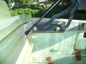
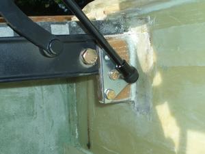
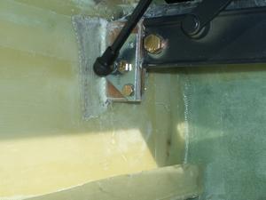
This is how I attached a ball to the hinge bracket for the gas spring. The ball is attached to a plate, which was purchased from McMaster Carr. If link is not working, here is the drawing for the part: Ball Mounting Hardware.
The ball mounting hardware is mounted to a plywood bracket. The bracket has 2 layers of BID on all sides. It was then flox'd to the hinge mounting bracket and to the forward side of the instrument panel. The ball mounting bracket is 2 BID taped to both the instrument panel and the hinge mounting bracket.
Multiple Pictures of the Hinge Installation
Step 16 - Installing Fuselage Top
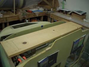
For a front hinged canopy, the fuselage top is part of the canopy. It opens and closes with the canopy. It is not a separate piece as when using a side opening canopy.
Step 17 - Canopy Lip and Instrument Cover
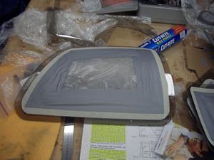
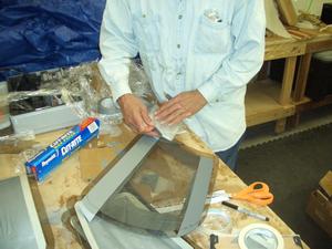
The instrument cover was very easy to make. Jeff had the idea of using the inside of the canopy, the part that goes over the instruments, as the mold to make the instrument cover. We put a layer of plastic wrap on the inside of the canopy cover. Then we layed 2 layers of BID on top. Once cured, we popped it out and most of the instrument cover.
The next step was to make a foam mold over the instrument panel so their would be enough room for the switches and anything else that was mounted on the top center portion of the instrument panel. The foam was covered with clear tape to act as a release, then two BID layers were layed on top of the instrument cover and over the foam. Once cured, it was popped out and trimmed to size.
To hold the instrument cover in place, three tabs were built on F28 to hold the instrument cover down. Then two tabs were mounted to the front of the instrument panel, near the longerons. Pockets were built on the bottom of instrument cover on the lip that extends one inch forward of the instrument panel. When cover is slipped into place, it is securely held in place without the need for any screws or bolts to hold it down.
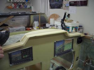
The main part of the instrument cover has already been made and is shown behind the foam. The visible foam is the part of the instrument cover which will cover the center switch area of the instrument panel. The foam on the forward portion of the instrument panel is the overhang to shade the instruments from the sun.
Step 18 - Installing Access Door
This step is still under consideration. At the moment, June, 2015, we are planning to have a key entry system that will directly unlatch the canopy, without the need for an access door. We are waiting till after the strakes have been installed to decide on the location of the key lock.
Step 19 - Installation of Canopy Latches
In this step, the canopy latches are installed. Since I am building a front hinge canopy, I need to have latches on both sides of the fuselage. All of the latches work by using one lever on either the pilot or co-pilot's side. This is accomplished by connecting the two sides together with a torque tube which is behind the seat back.
Step 20 - Safety Catch
I feel a safety catch is not needed with a front hinge canopy. In videos I have seen of the front hinge canopy becoming unlatched, the canopy opens about an inch and remains stable. There is no tendency for it to open any further.
Step 21 - Canopy Handle
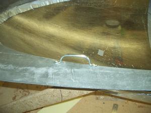
WoW! What a simple step! We bought a couple of screen door handles from Home Depot and screwed them in place. Not fancy, but functional.
Step 22 - Canopy Stop
I would like to be able to have the canopy open a few inches while taxiing in hot weather. The canopy stop I use may be similar to the one Uli Walters developed for the Cozy Classic or it may be a different design. As of June, 2015, this item is still under consideration.
Step 23 - Cockpit Ventilation
This step looks so simple in the plans. After all, it is only 2 paragraphs. So far, I have spent 38 hours on this step and I'm still not finished.
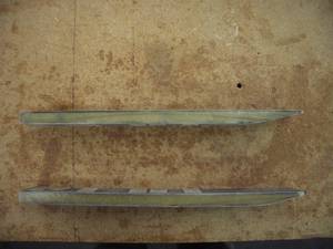
The step starts by building a NACA scoop to direct fresh air into the fuselage. The air then flows through a manifold to the fresh air vents in the cockpit.
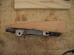
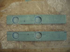
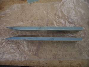
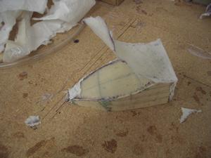
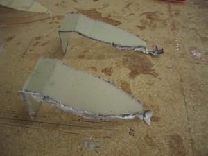
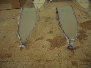
The plans have the form for the NACA built out of foam. I did this, but I could not get the edges as square as I liked. I then carved the form from a block of wood. It worked much better, however, when the fiberglass cured, I could not get it off of the form. I had to cut the block in half, lengthwise, then I could remove the fiberglass.
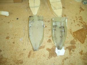
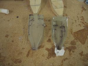
I thought I could put the two fiberglass halves together with BID, but that didn't work very well. I then made two new forms, out of wood. This time, I made only the top piece of fiberglass. After it cured, it was easy to remove as I had access to both sides. Once the fiberglass was free of the form, I put it back on the form and fiberglassed the sides. After curing, it was easy to break the sides free. Since the top had already been freed, it was easy to slip the NACA scoop off of the form. Afterwards, I discovered, I did not have to put fiberglass on the back of the form. If I had figured this out earlier, I could have made the entire NACA scoop in one layup.
The next piece is the interface to the fresh air vent. I used the plans fresh air vent (Whisperflo eyeball vent, model SW9977005-1). This vent is an inexpensive plastic vent. When the vent is closed, there is a 1/16 inch gap between the butterfly closure and the edges of the vent. This will allow air to enter the cockpit when it is closed. I believe I can fix this using a bead of silicon caulking, if it turns out to be a problem.
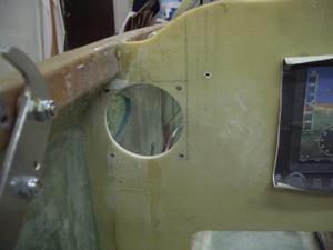
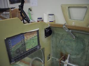
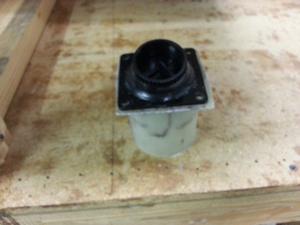
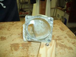
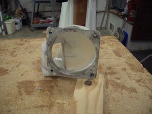
I wanted the vents to be removable, in case I didn't like them. My first thought was to use anchor nuts attached to the back of the instrument panel. However, they would be in the way when making the connection from the NACA scoop to the vent. Fortunately, I read on Wayne Hicks' website a way to make a flange that fits great behind the instrument panel and interfaces well with the fresh air vents. On the back of the flange, I mounted anchor nuts. This will make it easy to remove the fresh air vents, if needed. I detail how to make the flange in the pictures below.
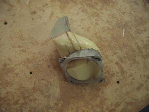
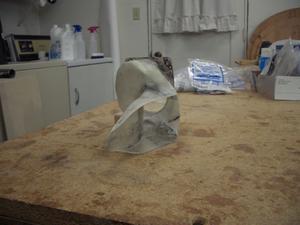
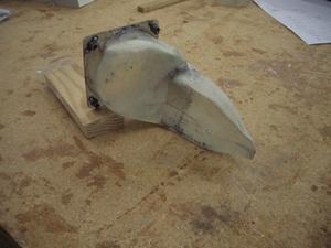
The last piece to make is the manifold between the NACA scoop and the flange for the fresh air vent. To make this I temporarily mounted both the NACA scoop and the flange. I used a cleco to mount the NACA scoop and mounted the flange on the back of the instrument panel using screws. Once these two pieces were in place, I cut out the a portion of the flange till I had an area that would be easy for the air to transition from the scoop to the flange. To connect the NACA scoop to the flange, I put multiple tongue depressors between the flange and the NACA scoop. These were 5 minute epoxied in place on the inside of both the flange and the scoop. Once the epoxy had cured, I removed both NACA scoop and flange unit as one piece.
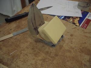
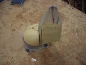
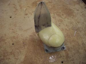
At this point, I had the NACA scoop and the flange attached by only a few tongue depressors. I needed to apply fiberglass between the two to make a manifold to channel the air from the scoop to the flange. This was done by placing foam between and inside both the NACA scoop and the flange. The foam was sanded to a pleasing shape. I then coated the foam with epoxy. Once cured, it provided a good surface for the box tape to stick to. I then placed two layers of BID around the foam, the scoop and the flange to make the manifold. When it had cured, I dug the foam out.
I then mounted the assembly onto the fuselage side using flox, per the plans. The flange was NOT epoxied to the back of the instrument panel as the screws for the fresh air vent will hold it in place.
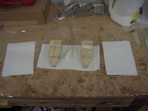
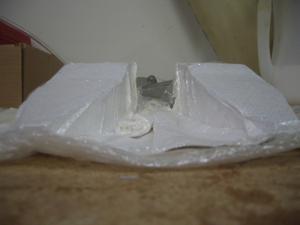
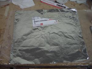
This is a perfect project to use the Cozy Girrrls' Lo-Vac technique. I placed the vacuum hose nozzle between the two NACA scoop forms. The paper towels are an inexpensive breather layer to allow the air to be removed when the plastic wrap is tight against the forms.
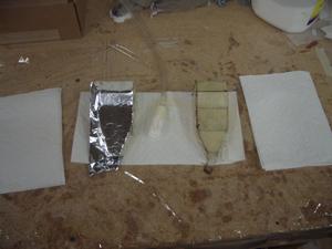
Wet fiberglass is being applied to the left form. The aluminum foil needs to be removed. The right form already has wet fiberglass on it.
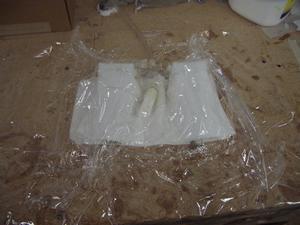
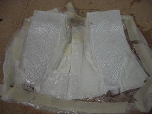
The vacuum pump has been turned on and air is being removed. The layers are:
- On the top layer is plastic wrap.
- Next is 2 layers of paper towels.
- Next is peel ply over the fiberglass.
- 2 layers of BID fiberglass.
- The wooden form is next.
- 2 more layers of paper towels.
- The bottom layer is plastic wrap.
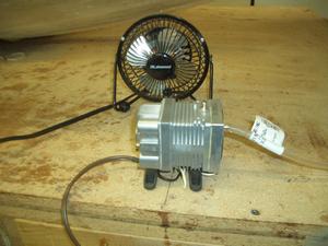
The small vacuum pump that I use. It is the one the Cozy Girrrls recommend. This is a medical pump and is not designed to be run continuously. The Cozy Girrrls recommend having a fan blowing on it to keep it cool.
One point I would like to mention, is this technique is based on using a small low power vacuum pump. The Cozy Girrrls describe it by saying "a mosquito can suck harder than this pump!"

Wayne Hicks kindly gave me permission to use this drawing from his website.
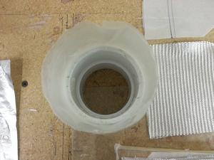
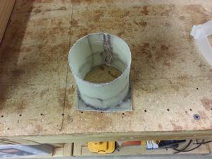
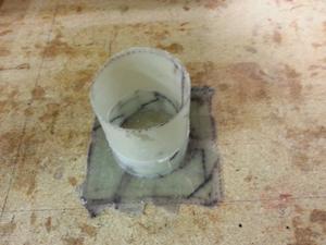
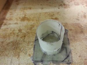
Following Wayne Hicks' lead, this is how I made the flange for the Whisperflo air vent:
- Two BID layers were layed down.
- Two BID layers were wrapped around a 2 1/2 inch (inside diameter) PVC coupling, then The PVC coupling is placed on top of the fiberglass.
- Two BID layers of one inch wide strips by 2 inches long, are placed around the PVC coupling.
- Two BID layers are placed over the bottom fiberglass (a hole is cut in them so they will slip over the PVC coupling).
- Two additional BID layers are wrapped around the PVC coupling.
- All of the fiberglass is covered with peel ply.
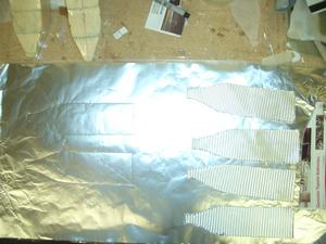
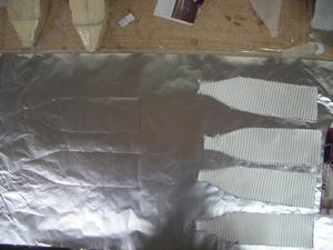
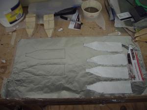
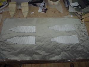
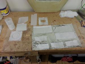
This is the fiberglass I cut to make the flange:
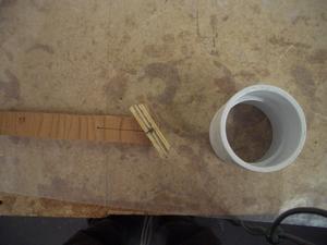
- On the upper left is the PVC coupling wrapped with 4 layers of wax paper.
- Middle left is a block of wood covered with wax paper with a piece of fiberglass on it. The block of wood was used so I could move the the unit to a heat tent (actually my epoxy warming box).
- Above the aluminium foil is the fiberglass with a hole in it so it will slip over the PVC coupling.
- The 4 small strips of fiberglass will become 2 pieces of 2 layers each. If you click on the photo to enlarge it, you will see the lower left two pieces have lines under them drawn on the aluminium foil that are 1 inch wide by 2 inches long. There are 5 on each strip for a total of 10 strips which will go around the bottom of the PVC coupling onto the base of the flange.
- On the upper right of the aluminium foil are the two layers that will be placed on the PVC coupling over the 1 x 2 inch strips.
- At the top left are the two pieces of peel ply which will cover the fiberglass.
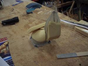
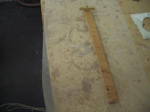
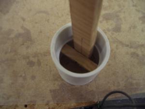
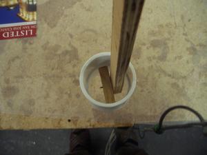
I forgot to take some intermediate pictures, so what you see here is pretty far along the process. There are 3 tongue depressors attaching the flange (on the table) to the NACA scoop (in the air). They were 5-minute epoxied to both the flange and the NACA scoop while both were in the plane. Once the expoxy had cured, the unit was removed so the fiberglass manifold connectiong the two could be made.
Foam was carved and put into the area between the flange and the NACA scoop. In this picture, I'm showing the foam attached and ready for sanding. Actually, some of it has already been sanded and a bit more foam was needed, so it was attached using 5-minute epoxy.
