Page updated on: June 6, 2012
September 13, 2012
December 3, 2012
December 15, 2012
Chapter 17 - Pitch & Roll Trim, Landing Brake, Center Console
Quick links within this page:
Step 1 - Roll Trim
Step 2 - Pitch Trim
Step 3 - Landing Brake and Center Console
Step 4 - Throttle Quadrant
Step 5 - Landing Light
Chapter Overview
In this chapter the pitch and roll trim systems will be built and installed. The roll trim handle is mounted on the instrument panel, just ahead of the throttle quadrant.
The center console will be built and the throttle quadrant will be installed.
I am going to implement the Davenport electrick pitch trim system and the plans manual roll trim. Pitch trim is used a lot and it is easier to use an electric system rather than the plans manual system. However, roll trim is seldom used and many flyers find the manual roll trim to be a good choice.
Pitch Trim Systems
Plans Pitch Trim System:
The plans pitch trim system works very well. However, an electric system is desired as there are a lot of pitch trim changes to be made. The pitch changes with both speed and turbulence. As it is constantly being adjusted, an electric system is preferred.
The disadvantage of the plans system is the use of two strong springs, one on either side of the trim bellhorn. If one breaks, then it takes a huge force on the stick as you must work against the remaining spring.
Davenport:
This uses a fiberglass flat spring which is attached to the elevator torque tube. It is 2 inches wide by 6 3/8 inches long and descends vertically from the torque tube. A 4 to 6-inch linear actuator (similar to the one used for the landing brake) is attached to the lower end of the spring.
The use of the Davenport spring allows the actuator to be manually over ridden, in the case of the actuator failing at maximum trim. If the spring breaks, then it is no longer connected to the elevator, so control forces would be the same, as if there were no trim system installed.
Plans for the Davenport spring may be found [here].
Strong Pitch Trim:
This is a ready to install pitch trim system that is a variation of Vance Atkinson's design. It has been modified and is being manufactured and sold by Alex Strong. The system is very highly rated, however, there are reports of hysteresis which makes it difficult to fine tune the pitch adjustment.
Linear actuators
Jeff and I decided a 5” stroke would be ideal, however, we could not find any 5“ stroke linear actuators. Fortunately, either a 4 or 6 inch stroke will work.
Force for the linear actuator needs to be at least 20 pounds. However, the linear actuators with this low of a force generally have a low gear ratio. This is a problem when fine tuning the pitch adjustment as a quick touch of the control will cause a large movement of the linear actuator. If the actuator is capable of providing 100 pounds or greater force, the gear ratio is usually a lot higher and fine adjustments are easier to make.
To better control the actuator, Jeff and I plan to build our own controller. The controller will determine the airspeed and then pulse width modulate the voltage to the linear actuator to allow for fine tuning of the pitch.
Key specifications of the linear actuator:
- Stroke: 4 to 6 inches
- Force: greater than 100 lbs (to get a higher gear ratio)
- Voltage: 12 V
- Potentiometer or limit switches (a potentiometer will allow the controller to determine the shaft position)
Companies we looked at were:
- I.E.I. (model LACT4P and LACT6P) light duty linear actuator
- Firgelli Automations (models FA-150-S-12-4 and FA-240-S-12-6)
- Thomson (models LA1-S-05 and LA1-S-06)
- Warner (models 01-D012-0100-A04-LNP and 01-D012-0100-A06-LNP)
Jeff and I decided to purchase the 4 inch I.E.I actuator. We liked it for several reasons. It had a built-in potentiometer so our custom control circuit would be able to determine the position. Also, the price was reasonable at $87 (June, 2012).
Roll Trim Systems
Plans Roll Trim System
This system works very well. Most flyers using the manual system say there is no need for an electric roll trim system. The roll trim may be adjusted only 3 or 4 times during the flight as fuel is used.
Hanka Roll Trim
The Hanka roll trim is not so much a trim system as a way of attaching a trim system or an autopilot to the ailerons. It is a thick fiberglass spring in the shape of a horseshoe. One end of the horseshoe attaches to the aileron push tube, either on the firewall or in the strake near the firewall, and the other end attaches to either a linear actuator or autopilot servo.
The advantage of using the Hanka spring is the failure is benign. If the spring breaks, the control forces do not become excessive. Also, if the linear actuator or servo breaks, it is easy to over power the spring.
John Basol used a Ray Allen T3-12A servo. This is a servo with a 1.2 inch travel. According to several sites, 1.2 inches was plenty.
The Roll Trim System we chose
Since the plans system seem to be very functional and most people like it, we decided it was the best way to go.
Step 1 - Roll Trim
Installing the plans manual roll trim system.
The plywood forms were custom made for my plane. The plans forms were close, but not close enough for my liking. After making many paperboard models, this was the shape I liked best. It is very slightly different from the plans.
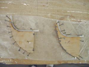
The nylaflow tubing was floxed to the form and these nails were placed around the form to hold everything in place until the flox cured.
This entire piece was made on the workbench. The nails are sticking into the workbench. After the flox cured, it was removed from the workbench and floxed into the plane.
Step 2 - Pitch Trim
As I mentioned above, my plan is to use the Davenport pitch trim system with a linear actuator. These are the steps I took to make the Davenport fiberglass spring.
I actually had to make the spring twice. The first time, I wasn't very careful in placing the UNI fiberglass around the large tube. When I clamped it down, the fiberglass became deformed. I tried to fix it, but with the number of layers of fiberglass and the short pot life of the epoxy (I was using a fast hardener) I just kept making it worse. When I realized it was a losing battle, I removed all of the wet fiberglass and threw it away. The next day, I tried again with much better results.
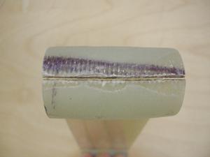
The wide black line on the spring was the center position of each of the fiberglass layers. I wanted to make sure I had all the layers centered as I applied them. I was using a fast hardener, so didn't have a very long epoxy potlife.
To remove the spring from the larger aluminum tube, I had to cut a straight line through the fiberglass using a dremel tool with a cut-off wheel. Once the fiberglas was cut through, I carefully worked the tube out of the spring.
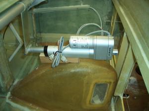
The pitch trim actuator in place, however, the aft mounting point has not been installed. The actuator is a 4 inch, 75 pound generic actuator. Jeff and I felt 75 pounds would be enough as the force on the elevators, as told to me by a couple of builders, is around 20 to 25 pounds.
The 4-inch lenguth of the actuator arm is 2 inches shorter than the max throw of the elevator. The Davenport spring will be positioned such that the center of the actuator arm is in the center of arm travel of the actuator.
Step 3 - Landing Brake and Center Console and
Step 4 - Throttle Quadrant
The landing brake extension mechanism, a linear actuator, was installed in chapter 9, step 6. This eliminated the need for the mechanical mechanism in the center console and made possible a custom design for the center console
I took advantage of this opportunity by designing my own center console. In the process, I incorporated the throttle quadrant in the design. Since both were designed and built at the same time, I have combined steps 3 & 4 into this one section.
The first step in the process was to build a cardboard mockup of the center console with the throttle quadrant. In the first version, the fuel valve was moved to the front of the console, similar to the way Wayne Hicks had designed his. After building the mockup, I found it was hitting my leg. I didn't like it. So I returned the fuel valve to the plans position.
In the second mockup, I had the center console the same width and height from front to back. The width and height was determined by the width and height of the throttle quadrant. I didn't like this either as the width of the console at the position of a person's hips was too wide.
The third mockup reduced the width of the center console aft of the throttle quadrant. The width was 1/2 inch wider than the heat duct. I had the sides of the center console on the outside of the heat duct. Ahhh, this was much better. I felt I had more room for my hips. However, the height of the center console was a bit high.
The fourth version lowered the height of the center console aft of the throttle quadrant. This was an improvement.
I was worried about the seat belt bolts going through the portion of the center console on the side of the heat duct. I felt it would be better to have the seat belts installed per plans. So in the fifth version, the portion of the center console aft of the throttle quadrant was narrowed so it was the same width as the heat duct. This placed the aft portion of the center console resting on the heat duct. This allowed obstruction free access to the seat belt bolt that goes over the top of the center console.
As you can see, this was an iterative process. I'm glad Jeff and I spent the time to make all the mockups as each one gave us more information as to what we liked and disliked. It was a bit frustrating as each mockup took about 2 hours to build.
The second step of the process was to use the cardboard mockup as a template for cutting foam and laying it out with all the angles needed to get the proper height and width.
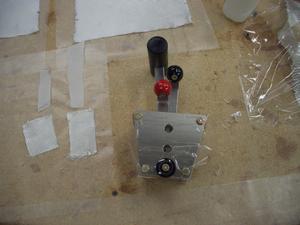
This is the Baxter throttle quadrant I am using. It is Model: TBS3NRI-F. The big knob on the side is the friction set knob.
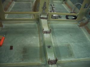
The brackets have been mounted onto the heat duct. This was done by first riveting the nut plates to the angle brackets (after match drilling the holes in the sides). Then the brackets were mounted to the sides. Flox was added to the brackets, then the sides were put in place against the heat duct. The next step is to add two layers of BID over the brackets lapping one inch onto the top of the heat duct.
Step 5 - Landing Light
The landing lights were installed in the nose of the plane. See chapter 13, step 10A for details of the installation.
End of Chapter Photo
Yea! Another chapter completed! I have completed 3 chapters during the past year (2012). Chapters 14 (the spar), chapter 16 (control system) and chapter 17 (trim controls and center console) have all been completed. The next chapter, 18 (turtleback and canopy) promises to be a another fun chapter to work on.


