Page updated on: October 3, 2009
December 7, 2009
March 1, 2010
September 4, 2010
February 7, 2011
September 4, 2011
Chapter 13 - Nose, Nose Gear, Pitot, Rudder Pedals and Brake Master Cylinders
Quick links within this page:
Step 1 - Reinforcing the Fiberglass Nosewheel Strut
Step 2 - Fabrication of the NG-30s
Step 3 - Installing the Jack Wilhelmson Electric Nosewheel Assembly
Step 4 - Installation of the NG-30 Box Assembly on the Fuselage
Step 5 - Nose Floor and Sides
Step 6 - Installing the Rudder Pedals
Step 7 - Installing the Master Brake Cylinders
Step 8 - Completion of the Nosegear
Step 9 - Piping the Pitot and Static System
Step 10 - Closing the Top and Carving & Glassing the Outside
Step 10a - Landing Lights - How to remove
Step 11 - Manufacturing the Nose Door
Chapter Overview
In this chapter, I will build the nose gear box which contains the nose gear strut and the retraction assembly. The nose box consists mainly of two glass/foam/glass side panels with built-in hardpoints for mounting the nose gear hardare. At the aft end, the side panels are mounted on F-22. The nose bulkhead, F-0, is mounted at the forward end. The nose floor and side pieces are constructed of urethane foam, epoxied in place and then glassed on the inside.
In a deviation from the plans, I am installing the Jack Wilhelmson electric nose gear. This will require one additional hole on one side of the NG30.
Another change is using Jack Wilhelmson's MKNG6 nose bearing. This bearing has been engineered to minimize the wear caused by the strut. On the standard bearing, this wear has led to the nose wheel wobbling. Jack's uses a tapered bearing that is a tighter fit and minimizes wear.
The pitot-tube piping and rudder pedals are then installed. The top foam piece is then in place, the outside is carved to shape and then glassed. An access door is cut in the top (a second door for the ballast comparment is optional) and removed to fabricate door falnges. The bottom of the nose gear box is closed off by installing a strut cover and a nose wheel well.
The brake master cylinders are installed to the rudder pedals. This is going to require quite a bit of thought as I'm using the Matco brake master cylinders and they are different from the plans master cylinders. The toughest part is making sure there is a 2.5:1 mechanical advantage to ensure there is enough braking power.
Step 1 - Reinforcing the Fiberglass Nosewheel Strut
The NG1-L strut is a high pressure laminate of S-glass uni-directional rovings. Although tremendously strong, it can be delamintated (split) by extreme bending loads. It is therefore necessary to wrap it with 2-plies of BID to protect it against splitting and to give it added torsional strength.
Step 2 - Fabrication of the NG-30s
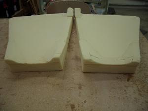
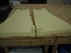
The NG-30s are the sides of the nose box. They will be made from H100 PVC foam and fiberglassed. Hard points for the nose gear and the nose gear retraction system will be installed prior to attaching it to the fuselage (F-22).
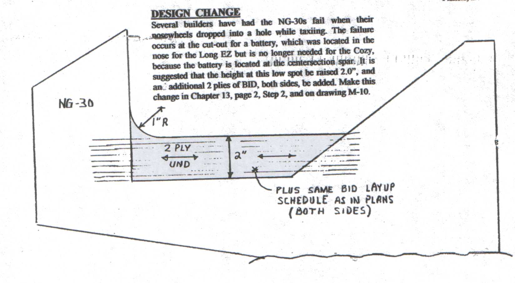
DESIGN CHANGE (From Cozy Newsletter #86; July 2004; Page 11)
Click the above drawing for a larger view. NOTE: The text above the drawing says the additional two plys should be "BID", however, the drawing shows them as "UND". "UND" is the correct one to use.
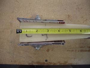
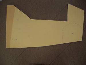
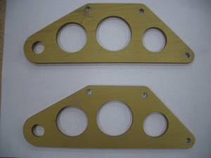
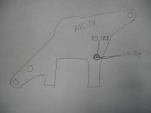
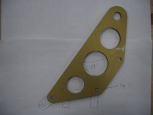
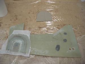
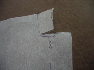
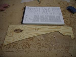
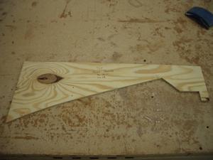
This step was time consuming, but easy to do. The hardest part was figuring out the location of the additional hole for the Jack Wilhelmson strut. The plans method has one less hole for mounting the nose gear retraction mechanism on one NG30 than on the other one. The plans method of determining the location of these holes was to use the NG51 as a template to mark their location. However, I do not have a NG51 as it is not needed when installing the Jack Wilhelmson electric nose gear. If you look at the pictures below, you will see that I copied the NG51 from the M-drawings. However, the NG51 is missing one hole. I had to overlay Jack's mounting plate to optimize the location of the missing hole.
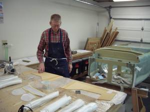
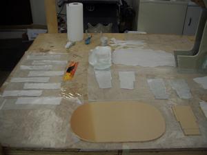
One area where a lot of builders deviate is making the hard points for the nose gear retraction mechanism. The plans have you cut out around 30 individual circles of BID and 15 oval pieces of BID to make the hard points. Many builders make a single large rectangular block of fiberglass. Then they use a hole saw to cut out the individual hard points and pop them into the appropriate locations on the NG30s. I felt this would be a bit of extra work, so I just used the plans method. It didn't take very long to cut out the BID hardpoints. I did it while watching a TV show.
Step 3 - Installing the Jack Wilhelmson Electric Nosewheel Assembly
This step is broken into two parts. The first is assembling the NG30s and attaching F0 to them. The second is installing the electric nosewheel assembly. I have delayed installing the electric nosewheel assembly until I have the the NG30s mounted on the fuselage.
Step 4 - Installation of the NG-30 Box Assembly on the Fuselage
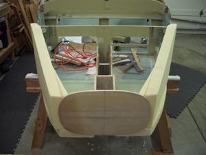
The mounting of the nose box assembly onto the fuselage was very straight forward. Having already fiberglassed and floxed both F0 and F5 to the NG30s made attaching the box to the fuselage a little bit easier.
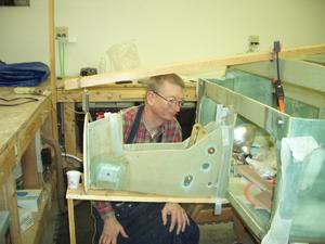
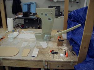
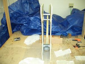
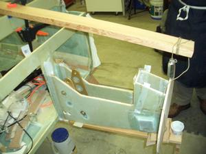
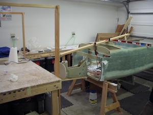
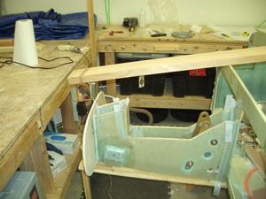
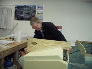
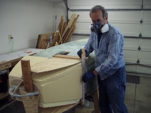
Here I am inspecting the positioning of the box after floxing and fiberglassing in place. The assembly is held in place by having it rest on the plank shown below the assembly. The plank is held on the bottom of the fuselage. It is resting on a saw horse which is supporting the fuselage. The forward end of the plank has a leg attached to it.
Step 5 - Nose Floor and Sides
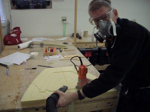
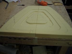
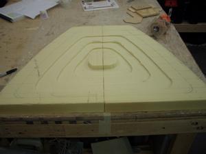
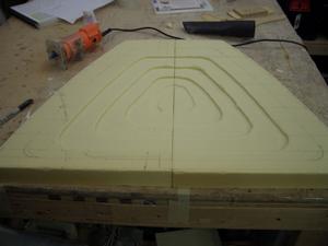
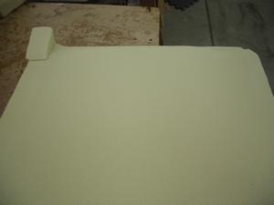
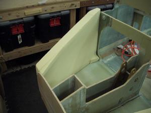
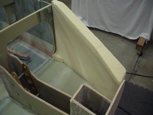
Manufacturing the sides was rather intimidating, however it turned out to be pretty easy to do. I was concerned about my ability to make a smooth contour of the sides. I called my buddy Neil, who is building a Cozy MKIV in Albany, California (near Berkeley), and asked him if he would like to come help. Neil has always been good about helping me with the more difficult parts of construction, for which I am very grateful.
Neil came down on a Saturday and we had the two sides whipped out in about 3-hours! It was pretty easy and it was fun.
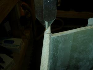
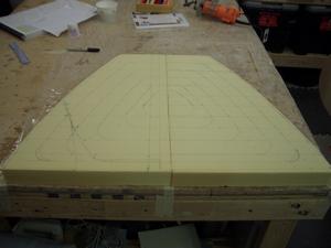
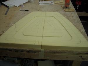
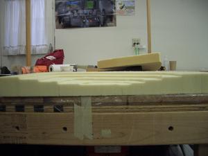
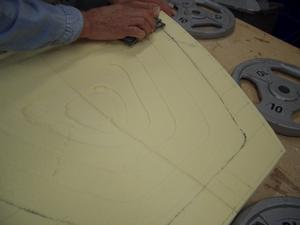
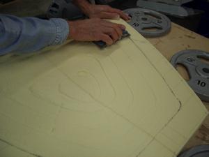
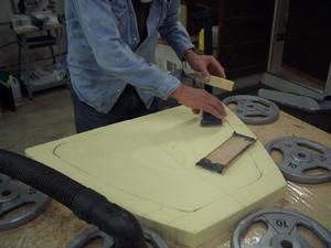
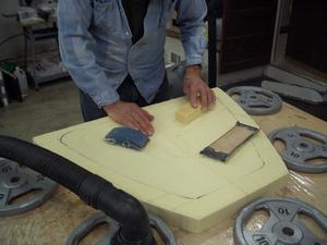
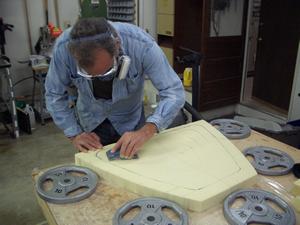
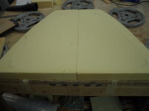
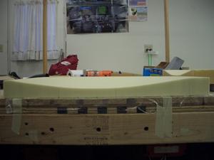
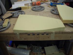
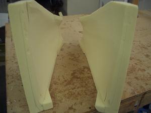
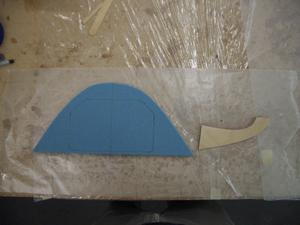
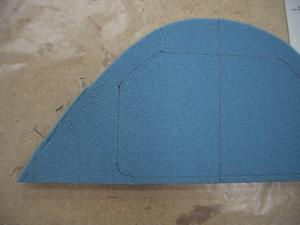
The key was to use a router to route the foam to the proper depth. Then, sandpaper was used to sand down the "steps" to make a smooth transition. Take a look at the pictures and think you'll see what I mean.
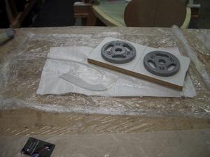
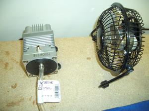
Both NG-31 and NG-32 need to be fiberglassed. I thought this would be a good chance to try out the lo-vac method pioneered by the CozyGirrrls. I had been wanting to try this method for some time, however, didn't want to practice on critical parts. This was the perfect chance to try it out.
Whoo hooo, it was a success! Lo-vac is really neat and worked great! I'm glad I gave it a try as I now have another tool to use when working with fiberglass!
Step 6 - Installing the Rudder Pedals
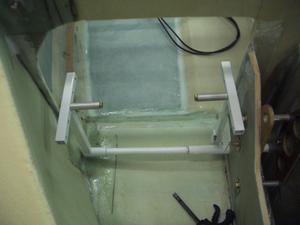
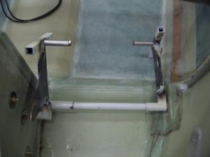
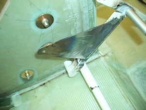
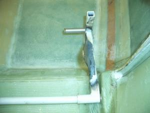
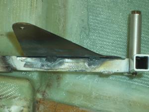
My original plan was to use the Dennis Olemann rudder pedals with the the Matco laydown master brake cylinders. While studying the Matco application note, I found they really stressed having a 2.5:1 mechanical advantage. This is to insure sufficient pressure was developed in the master brake cylinder to fully engage the brakes. An analysis of the Dennis Olemann brake pedals showed the mechanical advantage to be around 2.2 to 1. I then analyzed the plans design and sure enough, the mechanical advantage was 2.5:1. Hmmmm, what to do? I decided to use Dennis' rudder pedals, but to modify them to have the tabs for the master brake cylinders in the plans location. This meant welding on new tabs to the lower portion of the pedal arm.
Step 7 - Installing the Master Brake Cylinders
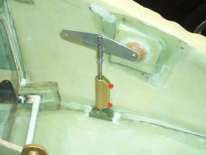
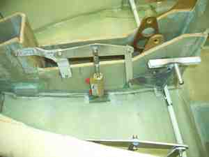
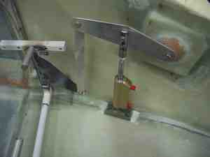
In this step, the master cylinders are mounted. As noted in step 6, I have decided to use the plans mounting method. The main reason is to meet the Matco recommendation of having a 2.5:1 advantage when depressing the rudder pedal. A secondary advantage is both the left and the right brakes will feel the same and need the same pressure to actuate the brakes. This is assured since both the right and left master cylinders are mounted on the pilot side.
Many builders have mounted one master cylinder on the pilot side and the other on the passenger side. This has resulted in having a different feel for each brake. The reason is due to the torquing of the tube connecting the the rudder pedals between the pilot side and the passenger side. By mounting both master cylinders on the pilot side, this problem will be eliminated.
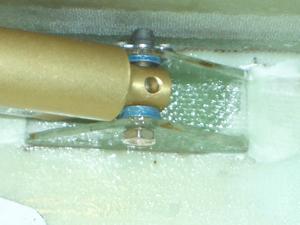
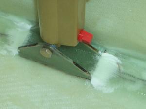
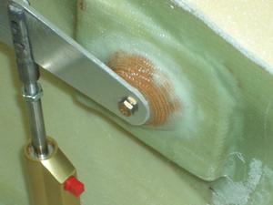
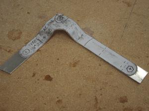
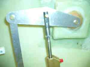
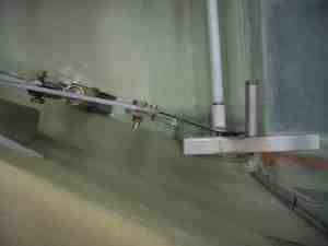
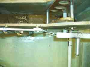
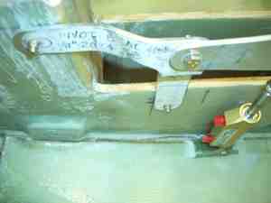
The downside of mounting per plans, is the complexity. Several connecting rods and trianglular lever arms are needed to connect the rudder pedals to the master brake cylinders. This requires a few more mounting points on the fuselage to hold this mechanical system. Fortunately, it was pretty easy to do, but a bit more time consuming.
Step 8 - Completion of the Nosegear
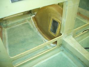
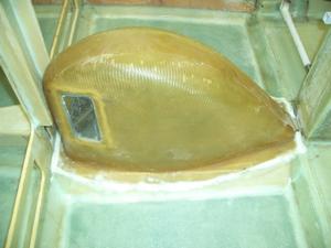
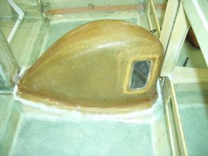
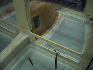
In this step, the nose strut cover and the nose wheel cover are installed. The nose strut cover was purchased from Featherlite. It just dropped into place and was floxed in. It was a bit short, so I added some fiberglass to the aft end to make it about 2-inches longer so it would reach F-22.
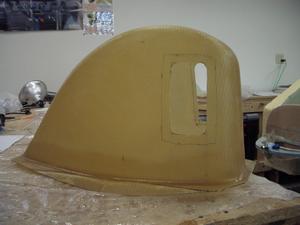
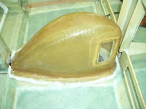
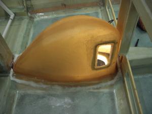
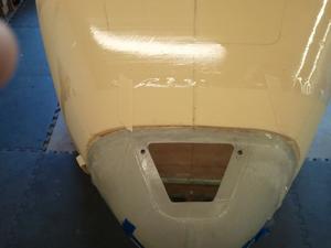
The nosewheel cover was a bit more complicated. It was also purchased from Featherlite. The one inch flange around the bottom of the cover was larger than the center section of the nose, which is about an inch higher than the floor of the fuselage. To get it to fit properly, Jeff and I heated the flange and bent it to the proper shape. When it cooled down, it was a perfect fit. Of course, this took many small tweaks to get it to fit.
Once the flange fit well, it was time to add windows on either side. The purpose of the windows is to allow you to visually verify the nosewheel has been extended or has been retracted.
I purchased the clear plastic windows from a local plastics shop. I dug around in their scrap bin and found a piece that was 1/8 inch thick and large enough to make two windows. The cost was 50 cents for the piece.
After reviewing many websites on how to install the windows, I chose to follow the method Bernie Siu used (see Bernie's chapter 13; step 8 for details).
Like Bernie, I made the window a vertical 2 x 4 inches. The size of the plastic is 2 1/2 x 4 1/2 inches so it will overlap all sides by 1/4 inch. The window is attached by floxing it to the inside of the nose wheel cover and then applying a 2 ply BID tape on all sides.
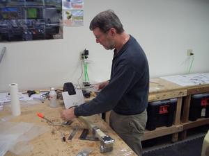
Jeff is checking the fit of the aluminum nose wheel cover before we install the sturt on the fuselage.
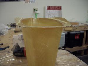
When we purchased the nose wheel cover from Featherlite, the flange was flat. This kept the cover from fitting on the center section of the fuselage, which is about one inch higher than the floor. To make a good fit, Jeff and I heated the flange and bent to the same shape as the center section of the floor. In this picture, you can see how much the flange had to be bent.
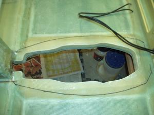
This is where the nose wheel cover will be placed. The black outline on the fuselage floor is the outline of the flange for the nose wheel cover. Notice how a portion of the flange is on the sloping section of the center section where it slopes to meet the floor of the fuselage. The center section is about one inch higher than the floor of the fuselage.
The twisting wires are the coax cable for the two antennas I installed on the bottom of the fuselage. They come up on the passenger side and are temporarily being stored in the heat tube in the center of the plane.
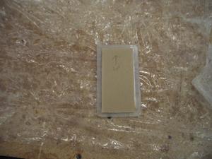
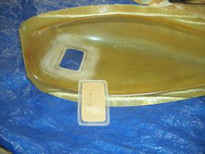
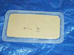
This is the plastic window. The protective paper has been cut back 1/4 inch on all sides so it can be sanded and then floxed to the nose wheel cover.
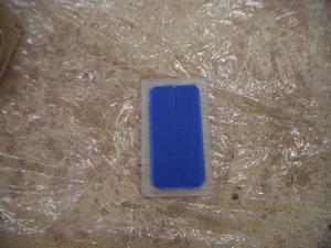
I was anxious to see what the plastic window looked like, so I had removed the the brown paper protective cover. To keep the window free of epoxy, I recovered it with blue painter's tape. When I did the other window, I left the brown paper protective cover on both sides till after the epoxy had cured.
Step 9 - Piping the Pitot and Static System
The installation of both the pitot and static tubes went easily using the plans method. I chose to install the removable pitot tube. The plans show the fitting for the removable portion of the pitot tube flush with the nose. I extended mine out about 1/2 inch. I'm hoping that this will be enough that I won't need to use the removable portion.
The only change I made in the installation of the static port, was to add a second static port to the right side of the aircraft. This will be used as a backup port.
Step 10 - Closing the Top and Carving & Glassing the Outside
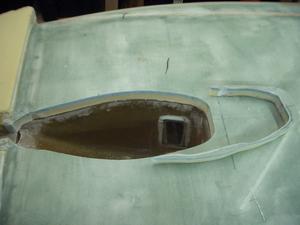
A couple of items are completed during this step. The bottom of the nose wheel bay is enlarged to the size of the nose wheel cover. The aft end of the nose wheel bay out is rounded to reduce drag from the air coming out of the nose wheel bay. The edges of the nose wheel bay are covered with fiberglass to protect the foam. The bottom of the nose is shaped. WoW! That is a lot!
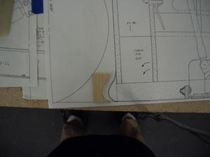
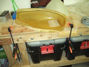
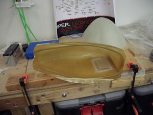
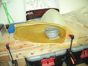
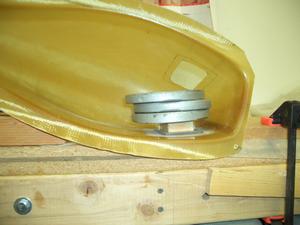
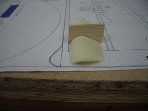
The aft end of the nose wheel bay has a very sharp edge on it. By shaping a piece of foam to a more aerodynamic shape, the drag of the exiting air can be reduced to 1 mph. This photo shows the plans shape. I made a template from a scrap piece of wood. I then rubbed this template against a piece of foam to shape it.
Shaping the nose sides and bottom
I am not a very artistic person. The thought of rounding the nose really terrified me. Then I came across Bernie Siu's website and was able to turn part of the task into a job any left brained person could do. See Bernie's website, chapter 13; step 10 for details.
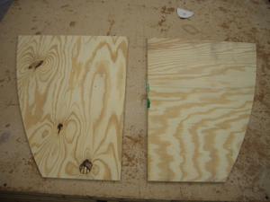
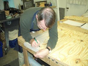
The process is to place a piece of paper on the floor under the nose. Then, using a string and plumb bob, mark the sides of the fuselage that curve, just before F22 on the paper. Then to do the same thing using the nose as the template by following the curve of NG31 (just forward of F0). Once this has been completed on both the left and the right sides, I put the paper on the work bench and had Jeff draw a curve connecting all the dots between F0 and F22. We then chose the side we liked best and used it to make two identical plywood templates of the curve. Be sure to carefully mark the centerline on both the template and the fuselage so the template can be accurately moved from side to side.
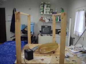
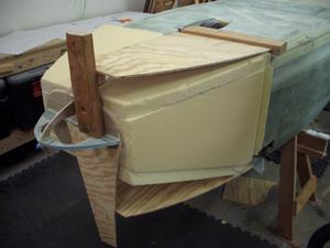
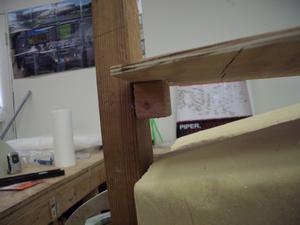
The wood templates are attached to the fuselage, one on top and one on the bottom. Note the fuselage must be level, in both directions. The templates must also be level in both directions.
Once the templates are attached, a sanding stick can be used to sand the sides to the same curvature as the templates. When one side is completed, the templates are moved to the other side and the sanding repeated.
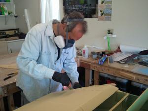
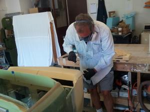
When the curvature has been established, I brought in Neil to round the bottom edge. Neil did a much better job than I could have done and it turned out GREAT!! Thank you Neil!
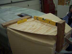
The templates are level in both directions. This is necessary to get the proper curve for the sides.
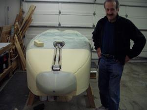
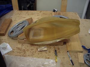
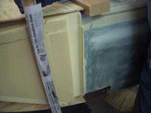
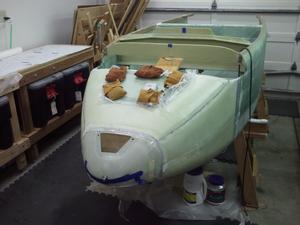
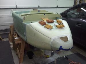
Neil has just completed the rounding of the corners of the bottom of the nose. We did run into a problem. The micro I used to attach the various pieces of foam together is now creating a problem. Micro does not sand very well. I had to dig it out using a dremel tool. My plan is to fill this area with micro before covering with fiberglass.
Making the nose cone door
Now that the nose bottom has been shaped, it is time to finish constrution of the featherlite nose cone. I need to cut out the door and create a easy method to open and close it.
The method I chose was to copy Marc Zietlin's method. His idea was to put a lip on the front of the nose cone door that would capture the front of the opening. I liked his idea very much and copied it.
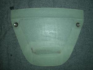
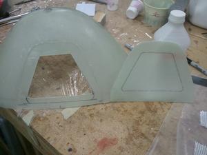
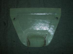
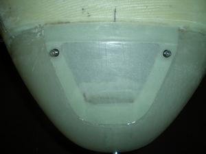
The outside of the completed door. The holes for the screws have been drilled. The holes have steel hardware store finishing washers, which have had the outside edge filed off, floxed to the door. This is to protect the fiberglass from wearing down due to repeatedly removing and replacing the screws holding the door to the nose.
Landing Lights - How to remove
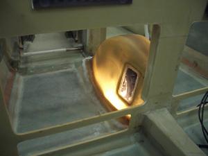
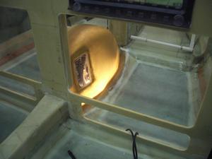
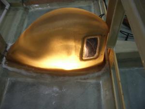
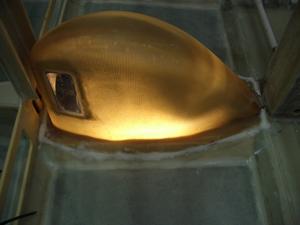
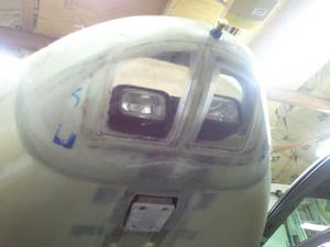
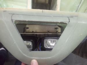
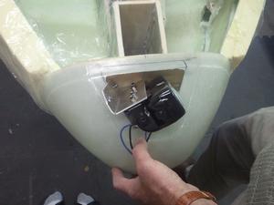
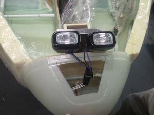
The next item is to install some landing lights. I chose to install them in the nose as it seemed simplier than using the plans method. I purchased two after-market lights designed for use on trucks. They are 55 watts each, which is the maximum allowed for use on motorized road vehicles in the USA. I fabricated an aluminum bracket and attached them to the bracket. The bracket is attached to F0 using two screws from the aft side of F0 which are screwed into nutplates on the forward side of the bracket. Next I cut two holes in the nose cone and flox'd plexiglass into them. The plexiglass is held in place by both flox and 1-ply of BID.
I wasn't very careful when I installed the plexiglass landing light lens in the nose cone. The result was a lot of epoxy smudges on both the inside and the outside of the lens. After the epoxy had cured, I sanded the smudges with 1200 grit sandpaper. Then I polished them using Novus 3 and Novus 2 plastic polishing compound to remove the scratches from the sand paper. It took a couple of hours, but they look great now.
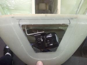
The landing lights were designed to be removed through the nose door for maintenance. Unfortunately it is a tight fit and there is only one way to remove and re-install the lights. I have documented the procedure here so I will remember how to do it, should the need arise.
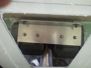
The screws holding the bracket on are removed. They can be easily reached through the nose hatch (not the nose cone door). The nose hatch is the large door just forward of the canard.
Note the nut plates that are riveted to the light bracket. I felt it was easier to attach them to the aluminum bracket rather than figuring out a way to attach them to F0. I'm pleased with the way they turned out.
Shaping the top of the nose
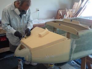
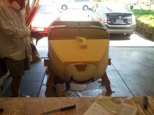
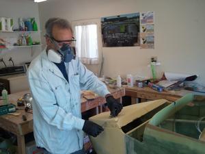
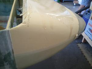
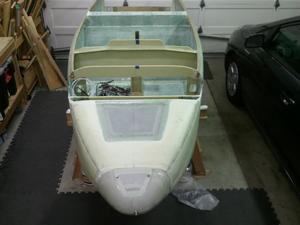
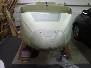
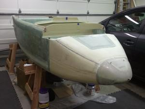
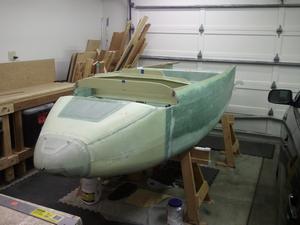
The final part of this step is to round the top of the nose. Again, since I am not very artistic, I prevailed upon Neil to help me out. Neil did a GREAT job of rounding the nose. He says he is practicing on my plane as he is on chapter 13 also.
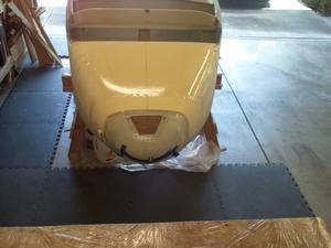
All done! Hmmm, I guess that was a little quick. In between the slicing off of the foam and this picture, there was lots of sanding using a variety of tools, such sanding blocks and small pieces of sand paper.
Doesn't Neil have a wonderful eye when it comes to shaping the nose? I *think* Neil is now prepared to shape the nose on his Cozy! Thank you Neil for your help!
Step 11 - Manufacturing the Nose Door
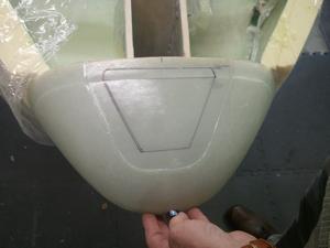
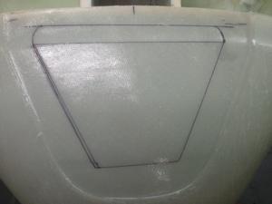
The making of the nose hatch door was a bit intimidating after reading the instructions. However, it turned out to be simple when taken step by step.
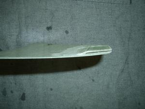
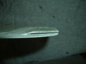
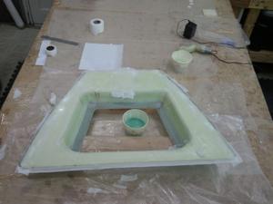
I did make a couple of minor changes. On the inside of the nose hatch, the plans say to layup 3 plies of BID along the edge to strethen the hatch opening. I liked Bernie Siu's idea of laying up much more and then routing out a hole and burying gasket o ring cord stock to provide a good seal between the door and the opening. His description may be found in section titled "Glassing In The Support Flange" on his web page. I ended up with a total of 20 layers of BID. This is close to a quarter inch thick.
Chapter Conclusion
Whew! This has been a long chapter. I started on it two years ago, in September 2009. During that time, I lost some enthusiasm for the project. However, with Jeff coming over every Tuesday evening to work on the project, progress continued, though for awhile it was only worked on once a week. Thank you Jeff for keeping the encouragement going!
About a month ago, I decided I wanted to finish this chapter before I left on a trip in September, 2011. I worked almost every day between 4 to 6 hours a day for three weeks. I not only managed to finish chapter 13, but also completed half of chapter 14. I'm hoping this new found enthusiasm will last through chapter 14 and through completion of the project. Wish me luck!
