Page updated on: June 6, 2012
September 12, 2012
December 15, 2012
Chapter 16 - Control System
Quick links within this page:
Step 1 - Pivot Mounts
Step 2 - Fabrication of Pitch and Roll Parts
Step 3 - Assembly of Pitch and Roll Parts
Step 4 - Installation of Pitch and Roll Assembly
Step 5 - Routing and Rigging the Rudder Cables
Step 6 - Rudder Stops and Brakes
Chapter Overview
This chapter will be fun! It is the construction, rigging and installation of the pitch, roll and yaw control systems. These are the main control systems for the plane. It includes the controls for the elevator (pitch), ailerons (roll) and rudder (yaw).
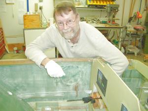
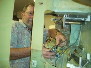
The lead for this chapter is Jeff. I will be his worker bee following the direction he sets. The reason for this is his extensive knowledge of working with metal. I feel more comfortable with him taking the lead for this chapter.
Since a lot of this work is being done at Jeff's house, the hours for this chapter are not accurate. I only logged the hours when work was done on the fuselage. The work we did in cutting the tubing and drilling the holes in them were not logged.
Step 1 - Pivot Mounts
The mounting brackets for the pitch and roll controls were made. The only change from the plans was to use metal bearings instead of the phonelic ones called out in the plans.
Step 2 - Fabrication of Pitch and Roll Parts
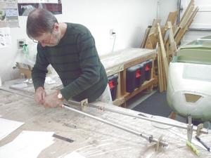
This step was cutting the torque and push tubes to length. Also, the holes for the bolts were drilled.
A lot of sanding of the tubes where they pass through bearings needed to be done as the tubes were a few thousandths too wide. Once we had sanded them down, they slipped nicely in the bearings.
Step 3 - Assembly of Pitch and Roll Parts
The fuselage portion of the pitch and roll controls were trial fit together. Only a couple of minor adjustments were needed. Everything fit together very well.
Step 4 - Installation of Pitch and Roll Assembly
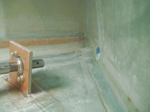
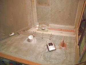
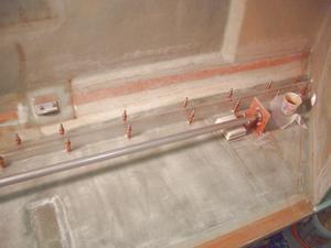
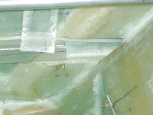
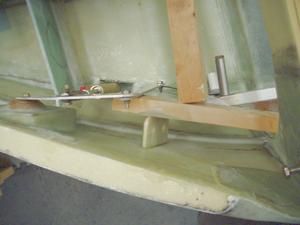
The pitch and roll controls were installed in the fuselage. The system was assembled in the fuselage then the various mounting blocks were floxed to the fuselage. Once the flox cured, the control system was disassembled and 2 plys of BID were applied to each side of the bearing blocks and overlapped onto the fuselage by 1 inch.
Step 5 - Routing and Rigging the Rudder Cables
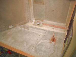
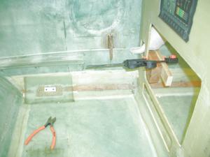
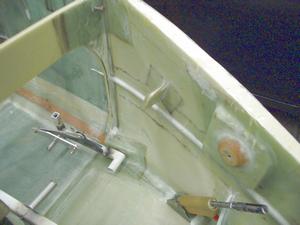
Both the electrical conduit and the rudder cable conduit were made and installed in the fuselage.
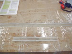
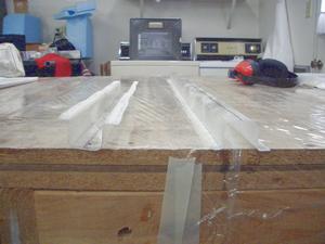
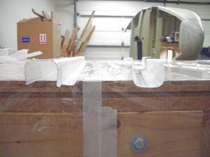
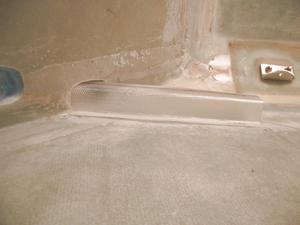
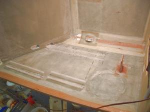
The electrical conduit was made by anchoring pieces of foam to the work bench. Then a layer of BID was placed over the foam. Once cured, the fiberglass was removed from the foam, cut to length and installed in the aircraft.
The electrical channel was run differently through the seat back on the two sides of the fuselage. The left side, has the conduit stopping at the seat back. There is a small gap between the seat back and the electrical conduit where the electrical channel runs through the seat back. I was worried it might be difficult to pass a wire from the back of the fuselage through the seat back as it might want to try to sneak out of the gap between the conduit and the seatback.
On the right side of the fuselage, I ran a piece of conduit through the seatback. To do this, I needed to enlarge the hole in the seatback. Also, I could only run a short piece of conduit through the seat back due to the curvature of the sides of the fuselage. The remaining conduit overlaps the portion going through the seat back, so there is no gap in the conduit at the seatback.
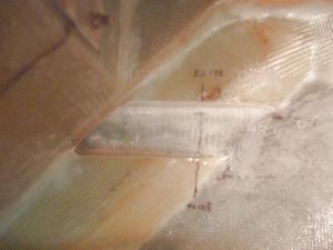
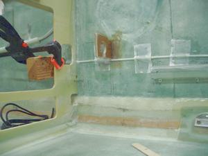
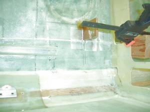
The rudder conduit was made from 3/16 nylaflow tubing. It was cut to length and then floxed to the electrical conduit. In several places, the conduit was attached to the fuselage using a piec of BID tape.
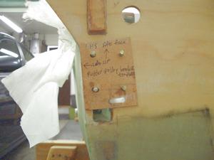
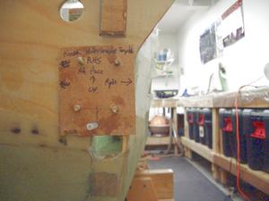
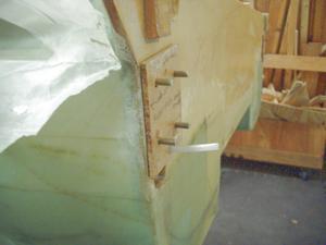
We had some trouble getting the rudder conduit to exit out of the electrical channel in firewall at the correct position. To solve this, we made two templates, one for the left side and one for the right side. This masonite template fit over the screws for the rudder pulleys and holds the rudder conduit in place while the flox cures.
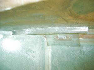
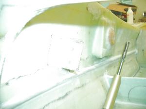
This is the left side of the fuselage where the conduit meets the seat back. On this side, I did not put a piece of the conduit through the seatback. Notice the small gap between the end of the conduit and the seat back. I was worried it would be difficult to feed a wire through the seat back as the wire migt try to come out of the conduit through the gap.
Step 6 - Rudder Stops and Brakes
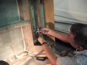
In this step, the brake lines will be installed. The plans specify using Nylaflow tubing, however many builders recommend using solid tubing as it will not wear out and will not deteriorate over time. I was initially planning on using 3/16 inch stainless steel brake lines. I had problems making the flare on the ends for the connectors. The flaring tool Jeff and I used was damaged as stainless steel was too hard for it. A flaring tool for stainless tool was very expensive, more than the cost of the tubing! As a result, I have decided to use 3/16 inch aluminum tubing.
Kevin Walsh put together a great list of part numbers needed for a hardline installation. Here is the list he sent out to the Cozy Builders mailing list on January 11, 2012:
Date: Jan 11, 2012 3:56 PM
From: "Kevin R. Walsh"
Subject: COZY: Stainless/Teflon & Aluminum Brake Line Part Numbers
It occurs to me that perhaps part of the resistance to using stainless/teflon flex lines and aluminum or stainless hard lines for the brakes might be that people do not know what to order. I am going to remove that hurdle:
- #3 Stainless Steel Braided PTFE Hose 3260-3-FOOT $4.59 25' will cover both lines from master cylinder to hard lines, and all the way from the bulkhead down the gear leg to the caliper. You might get by with 20', but 25 works for certain, and allows for errors.
- Straight 3AN Hose End for size #3 PTFE Brake Hose 3261-3-00 $5.99 eight are required.
From Aircraft Spruce aircraftspruce.com
- AN822-3D Elbow, -3 Flared Tube to 1/8" NPT AN822-3D $5.50 two are required. These go from the master cylinder to the PTFE/SS line. Order 4 if your calipers need these instead of the straight fittings.
- AN815-3D Union, -3 Flared Tube to -3 Flared Tube.
- AN815-3D $2.80 4 are required. These connect the PTFE/SS line to the 3/16" hard line at the front, and the 3/16" hard line to the PTFE/SS at the gear leg. You may prefer to use AN832-3D bulkhead fittings, especially at the rear bulkhead. Used at the front it also makes it so you can create a small flange to mount the fittings so it doesn't rely on the hard line to hold it in place.
- 5052-0 3/16" Aluminum Tubing 03-39200 $1.86/ft; Buy two 12 foot sections. It is OK to have them roll it for you. It unrolls just fine. If Aircraft Spruce won't roll it for you, I know Wicks will. If you really want stainless, it is 03-16020 at $4.97/ft. If you're going to do that, you could just as well use the PTFE/SS all the way and save some money on fittings.
- AN816 Nipple, -3 Flared tube to 1/8" NPT AN816-3D $1.56; Two are required. These go from the PTFE/SS line to your caliper. Depending on your caliper positioning, you might prefer an AN822-3D elbow. Here is a photo of ours, using the elbow.
- AN818-3D Nut, and Coupling Sleeve
- AN818-3D $0.47; 4 are required.
That is everything you need to order to go from the master cylinder to the caliper. I get a total of $234.51 plus tax, shipping, etc. The PTFE/SS is almost half of that cost. I strongly suggest that you consider purchasing Matco dual parking brake PVPV-D for $125.65. It will change your fitting requirement just a bit. You'll need 4 more AN816-3D fittings, but you can eliminate two of the AN815-3D (or AN832-3D if you so choose) unions.
--
Kevin
Jeff and I ordered these parts from Summit Racing in February, 2012:
- $14.95 ea (qty 1) EAR-63010114ERL – 14 inch hose (Master cylinder to brake line)
- $17.95 ea (qty 1) EAR-63010117ERL – 17 inch hose (Master cylinder to brake line)
- $5.95 ea (qty 2) FRA-482203 90 Degree, Male -3 AN to Male 1/8 in. NPT, Aluminum
- $3.95 ea (qty 4) FRA-483203 – bulkhead connectors (brake line termination in both nose and hell hole)
- $0.95 ea (qty 4) FRA-492403 – Nuts for the bulkhead connectors
- $35.95 ea (qty 1) SUM-220236 - Tubing, Stainless Steel, Natural, 3/16 in. package of 20 ft.
- $5.95 pk (qty 1) AER-FBM3669 - #3 AN tube sleeve; package of 6
- $2.95 pk (qty 1) SUM-220333-6 - #3 AN tube nuts; package of 6
- $11.95 standard delivery and handling ---------
- $120.75 total
Since the Stainless steel tubing did not work out, we ordered aluminum tubing from Aircraft Spruce
- $1.85 ft (qty 24) 03-39200 - Tubing, Aluminum 5052-0; 3/16 inch
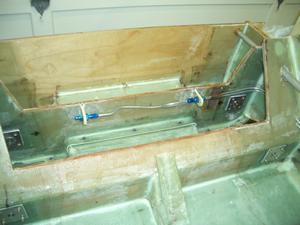
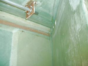
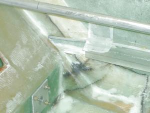
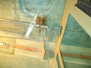
Completed brake line installation at the landing gear. The brake line is attached to the fuselage using one inch wide strips of BID.
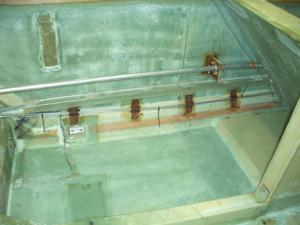
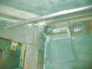
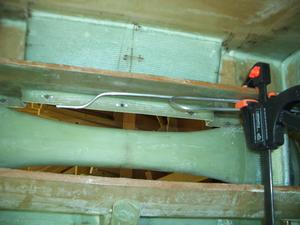
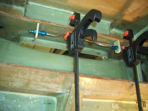
Completed brake line installation. This is where the brake line passes through the back seat area. It is attached to the fuselage using flox and 2-layers of 1 inch wide BID strips. The strips are placed a maximum of 11 inches apart, however, in most places, for convenience, they are 9 inches apart. At the strips, the brake line is flox'd to the fuselage.
The 11-inch maximum comes from an FAA publication which recommends supports for aluminum line be a maximum of 11 inches apart.
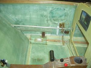
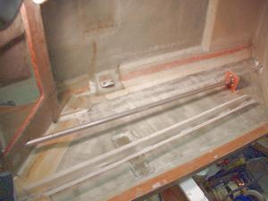
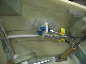
Completed installation of the brake lines as they pass through the front seating area. Ignore the center console. This picture was taken after completion of chapter 17.
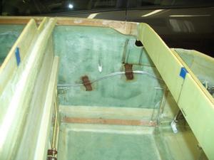
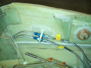
The brake line is passing through the area just forward of the instrument panel. The termination was shown in a previous picture.
Another chapter completed. On to chapter 17!
