Page updated on: September 4, 2011
December 8, 2011
January 16, 2012
Chapter 14 - Center Section Spar
Quick links within this page:
Step 1 - Center section jig
Step 2 - Assembly of foam parts
Step 3 - Interior layups
Step 4 - Install the forward face
Step 5 - Outside hard points
Step 6 - Spar cap layup
Step 7 - Shoulder harness & outside layups
Step 8 - Hardpoint reinforcements
Step 9 - Access for wing attach and end layup
Step 10 - Installing in the fuselage
Chapter Overview
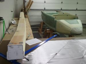
The center section spar is the heart of the wing attachment system. The spar is firmly attached to the fuselage at the firewall. The wings are then attached to the spar.
The top of the spar is perfectly flat. The bottom of the spar has a slight positive dihedral to allow the fuel to flow to the engine. The forward and aft faces of the spar sweep aft.
Accuracy is important in building the spar. The wings stretch 28 feet from wing tip to wing tip and even small variations in the spar thickness, dihedral or sweep will have a dramatic effect at the ends of the wings.
An accurate jig made of particle board is first constructed. Then the foam for the spar is matched to the jig. When all is in place, the interior of the spar is fiberglassed. Then the spar is removed from the jig and the outside spar is built and then the entire outside of the spar is covered in a layer of fiberglassed.
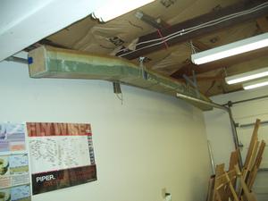
Per the suggestion in the plans, I do not plan to install the spar until the wings are completed. It is easier to match the wings to the spar before it is permanently attached to the fuselage.
Step 1 - Center section jig
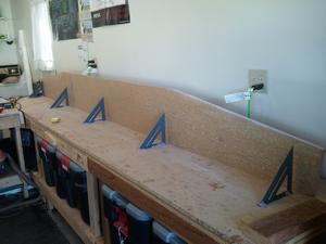
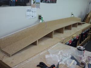
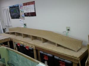
Building the jig was a lot of fun. It went together easily, but then, I like working with wood ;-)
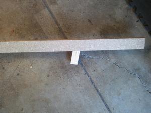
I was able to get all the pieces for the jig from one sheet of 8 foot x 4 foot x 3/4 inch particle board. I had Home Depot cut it on their saw that was designed for cutting large sheets of plywood. Before I went to Home Depot, I was thinking about the best way to have them measure for the cut. I didn't think asking the Home Depot staff to cut a strip of wood that was 8.51 inches wide would go over very well. To over come this, I made three templates out of wood. Each was in the shap of a "T". the top of the "T" would be placed along the edge of the particle board and the end of the stem of the "T" would be exactly the width I wanted the plank to be. I had templates for 2 inches, 8.51 inches and 12.5 inches.
I was very lucky when I found a salesperson to help me. Jeremy was a young lad and he was conscientious and very accurate. He spent a good deal of time making sure the cuts were just right. The templates made it easy as there was no measuring to be done. Just slap the template against the board and make a mark. Then adjust the saw to cut just barely shy of the mark. It took time, but it was easy to do.
The reason for the 2-inch template was to cut a strip off of one side of the particle board. Once the first cut was made, I was confident all the other cuts would be parallel to the first cut. I didn't want to take a chance their saw was not perfectly in alignment and this first cut would compensate for the saw blade not being perfectly parallel to the manufactured edge of the board.
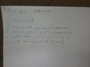
My cut list was:
- 1 strip 2-inches wide by 8 feet long
- 2 strips 12.5 inches wide by 8 feet long
- 2 strips 8.51 inches wide by 8 feet long
The remaining piece was about 4 inches wide by 8 feet long.
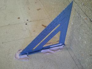
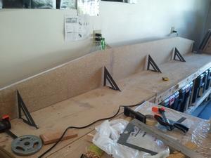
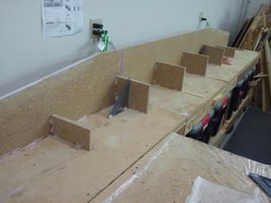
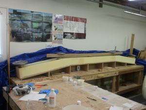
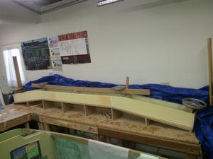
Before beginning to assemble the jig, I leveled the work bench in both directions. I also purchased five inexpensive framing squares from Harbor Freight. They were on sale for $2 each and they made it easy to get the 12.5 inch board (piece "D") square with the bench top.
To cut the angled part of piece "D", I used a portable Makita power saw. Even though I put a guide rail on the wood before using the saw, I still did not cut a very even line. I guess this was due to my unfamiliararity with the machine. I ended up creating a new edge by putting Bondo on the edge and sanding it smooth and straight.
Step 2 - Assembly of foam parts
This step was very easy and went quickly. The foam for the top, bottom, aft and forward sides of the spare are cut out. The top, aft and bottom sides are then micro'd together using the jig to maintain the proper posititioning.
The hardest part of this step is determining the location of the "top" and "bottom" sides of the spar. The aft is clearly defined in step one as "Caution! The spar is mounted aft face down in the jig, but all statements like “top”, “forward”, etc., relate to how it is mounted in your completed aircraft." Hmmmm, okay, which side is the "top" and which is the "bottom"? The only reference I could find was in step 2 on page 2. In a parenthetical comment, CS2 is mentioned as being the "top". Here is my take on the which is which:
- Top: the CS2 foam placed against piece "D" on the back of the jig
- bottom: the unsupported CS4 foam at the front of the jig
- aft: the CS1 foam on the shelf portion of the jig
- forward: the CS3 foam which will be placed on the upper part of the jig
Step 3 - Interior layups
This step took longer than I had anticipated. I spent just over 12 hours preparing for this layup. This included making the templates, cutting the fiberglass and designing a method to apply 5-pounds of weight to each hardpoint while the epoxy cured.
The actual layup took me another 12 hours, though I have seen websites where some builders have done it in as little as 4 hours, but most take around 7-hours.
The plans say to do this as one layup without curing in between. My first idea was to use the slow hardener and tackle this on two days. Using the slow hardener with MGS335 resin, it has been taking around 15 or more hours to cure. The temperature has been around 70 with it falling to the 50s at night. I wanted to start the layup in the evening, then go to bed. I would wake up the next morning and finish it. Unfortunately, the day I decided to do the layup, was the hottest day of the week. At midnight, the temperature in the work area was still in the 80s. I was worried it might cure before morning, so I push on through the night and finished at 6:30 AM. It was an exhausting night!
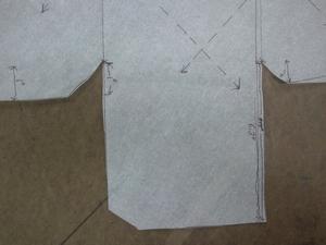
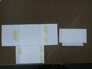
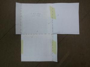
The two biggest challenges were determining the shape of the fiberglass to cut out and how to apply 5 pounds of weight while the layup cured. I neatly folded some tracing paper into the inside corners of the jig. Then unfolded the paper and determined the optimum shape for the fiberglass. I have photos of all my templates below.
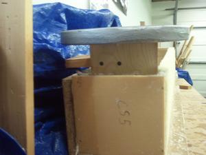
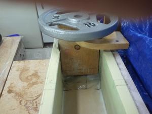
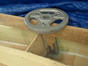
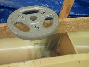
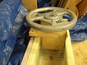
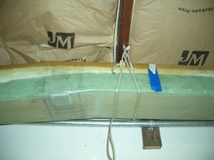
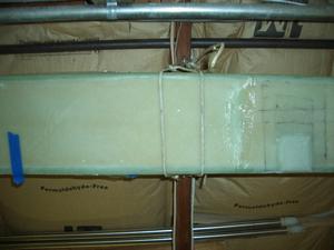
The five pounds of weight needed for the hard points while the epoxy cured was a bit more of a challenge. This required designing a method of suspending the weight above the hard points. Jeff and I came up with a design that worked very well. See below for photos of how we did it.
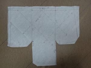
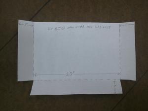
This is the ply of BID which lays against the bare foam. In the plans, it is called layup 2. The template shown is for the ends. The left edge, right edge and center bottom edge are attached to the open end of the spar. The center lays on the the aft side of the spar and the center lower tab on the template goes on the inside end of the spar. There is a one-inch overlap from the top and bottom sides to the end face of the spar.
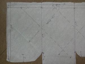
This is a closeup of the left side of the template. The left side goes along the bottom of the spar and the center lays on the aft side of the spar. The notches are there to allow for a one-inch overlap onto the end of the spar. Of course, top and bottom are interchangeable, depending on which end of the spar the template is being put on.
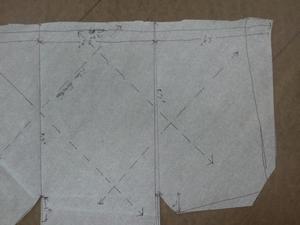
This is a closeup of the right side of the template. The right side goes along the top of the spar and the center lays on the aft side of the spar. Again, the notches are there to allow for a one-inch overlap onto the end of the spar. NOTE: The diagonal corner on the right lower edge should be filled in. The tracing paper I was using was just a little bit too small and the corner is missing.
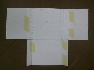
This is layup 4 for the ends. It is applied before the aluminum hardpoints are installed. The left edge, right edge and the bottom tab edge go along the open edges of the spar. The lower tab attaches to the inside face of the end of the spar. There is enough fiberglass to lap one-inch from the end pieces onto the top and bottom sides.
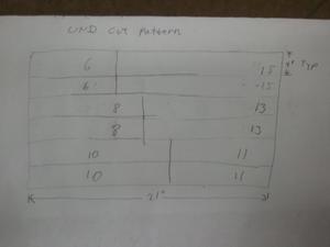
As I was looking at the UNI pieces to minimize the amount of fiberglass to cut out, I noticed that if the longest and shortest pieces were paired up, the total length would be 21 inches. Similarily, if the next longest and next shortest pieces were paired up, it again came to 21 inches. Finally, if the two middle pieces were paired up, it again came to 21 inches. This made it easy to cut out the UNI.
These pieces of UNI are used as reinforcement over the aluminun hard points located near CS4, CS5, CS7 and CS8.
As is my usual practice, I put a piece of masking tape (parallel to the long fibers) between each set of pieces. This holds the fibers on the edges together while being wet out. Once it is wet out on wax paper, the masking tape is cut off and the UNI is applied. Once applied, the wax paper is then peeled off.
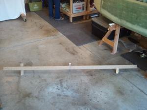
This is the contraption Jeff and I devised to apply 5 pounds to the aluminum hard points near CS5 and CS7. The vertical sticks, near the ends, rest on the hard points. The stick in the middle is screwed to the upright (piece "D") to stabilize it and keep it from falling over when the weights are put on the board. It is a flimsy stick as I did not want to affect the amount of weight being applied to the hard points.
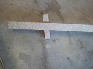
This is the left side. The vertical piece is screwed to the horizontal piece using two dry wall screws.
The vertical pieces need to be long enough for the horizontal piece to clear the CS5, CS6 and CS7 bulkheads. When we intially designed this, the vertical pieces were too short. After finishing the layups, I tried to put this contraption on the hard points, but the horizontal piece just rested on top of the interior bulkheads! I had to lengthen the vertical pieces to get it to work.
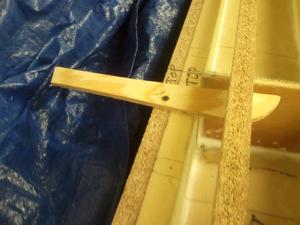
This is the stick being used to stabilize the contraption to keep it from falling over. The flimsy stick in the center is screwed into both the upright (piece "D") and into the horizontal piece of wood. This mechanism worked great as lots of epoxy was forced out from under the hard points due to the weight being applied.
Step 4 - Install the forward face
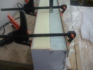
In step 4, the open side of the spar is covered in foam. Once the epoxy holding the foam together has cured, the spar is removed from the jig and the jig may be dismantled as it is no longer needed.
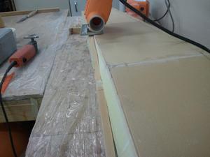
The spar cap troughs are made by sanding the soft urethane foam to get the correct shape. Finally, two of the corners of the spar are removed.
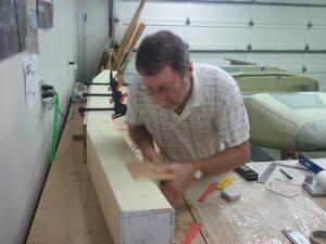
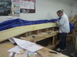
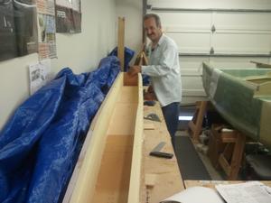
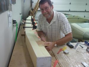
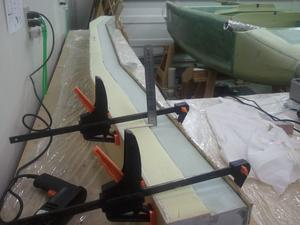
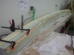
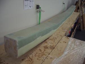
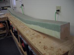
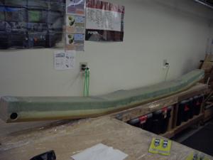
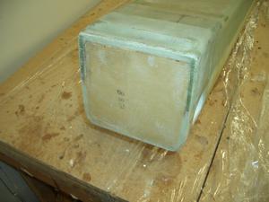
The spar is now completely enclosed and the jig has been dismantled. Jeff is making the spar cap troughs by sanding the urethane foam. The depth of the trough varys over the length of the spar as more layers of spar cap tape are placed in the center than at the ends. The depth is determined using templates that were made from the plans.
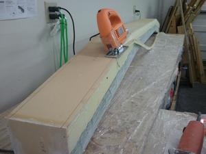
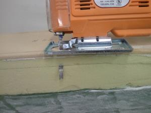
To make the angle cut on the spar was very simple. I made a line 1/2 inch from the edge on the forward side and 1 inch from the edge on the top side of the spar. On the end of the spar, I drew a line from connecting these two lines. The angle of the jig saw was set to match the line on the end of the spar.
Step 5 - Outside hard points
The outside hard points are added in this step. These hard points are made of aluminum and are placed directly over the inside hard points. Then a 4-layer shear web of unidirectional fiberglass is placed over the bottom spar cap trough, across the aft face and then over the top spar cap trough.
The shear web layup, with two people, took close to 5-hours to complete.
Step 6 - Spar cap layup
Before beginning the layup, dams had to be placed along the aft face of the trough so the spar tape would not fall out of the trough as each of the 23 layers of spar tape are added. I built the dams out of 1/4 inch plywood and used the Wayne Hick's method of attaching the dams by using drywall screws. These worked GREAT. The screws held the dams solidly in place and tightly against the aft face of the spar. The plans suggest using bondo, however, with bondo, you need to wait while it cures. Using drywall screws, there is no delay.
The top and bottom spar cap layups are huge layups. Jeff helped me for part of the top spar cap layup. Two of us worked on it for 5 hours and then I continued alone for another 5 hours. I couldn't believe how long it took!
For the bottom spar cap, 17 layers, Neil helped me for the entire layup. It took 5 hours to complete the layup. The only reason it went this fast was Neil, another Cozy builder, kept the speed up. He was pushing us as fast as we could go and it payed off! Otherwise, it would have probably taken a couple of hours longer.
Step 7 - Shoulder harness & outside layups
It is time to add the shoulder harness mount points and to do a 4-layer unidirectional fiberglass layup on the outside of both spar caps. The hardpoints are made from spruce and are embedded into the foam.
The 4-layer layup was another long one. It took around 8-hours to complete. This one was tough as I noticed I was about out of slow hardener. To make sure I had enough, I used a 50-50 mix of both slow and fast hardener. I'm using MGS L335 resin with the H340 slow hardener and the H355 fast hardener. With MGS, you can mix the slow and fast hardeners to control the pot life of the epoxy. Using a 50-50 mix dramtically reduces the amount of pot life of the epoxy. As a result, the fiberglass did not slide around as easily and it was harder to pull the fiberglass strands straight. Each piece of fiberglass had to have several small batches of epoxy mixed up as the pot life was about 15 minutes. This added extra time to the layup. I much prefer using 100% slow epoxy for these large layups. It makes the layup so much easier.
Step 8 - Hardpoint reinforcements
Using a file, I made a radius on the top edge of LWA2 as shown in section B-B. Also the top and the bottom edges of LWA3 (section C-C) was radiused to a 1/8 in. I cleaned and sanded them and then installed them with flox as shown in the section views. After cure, flox corners were made, and lay up #7 consisting of 3 plies UND 3 in. wide centered over LWA2 and LWA3 was installed as shown in Fig. 16. The layup was lapped onto the top and bottom at the outboard hard point, and onto the top at the inboard hard point. I then added 1 ply of BID 5 in. wide at 45 degree orientation, centered over the UND strips, only on the aft face. THe edges were peel plyed for a good transition and then allowed to cure.
Step 9 - Access for wing attach and end layup
Details of step will go here
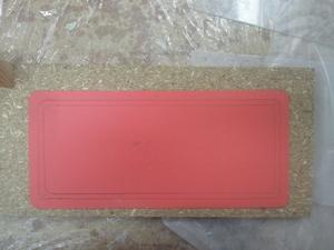
I made these patterns for the wing bolt access holes on the forward face of the spare. The inner area is the size of the hole. The middle area is the size of the glass to glass bond of the fiberglass. The outer area is the transition between the full thickness of the foam to zero thickness, where it meets the inner glass surface.
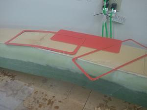
Next, I cut out each of the templates. The outside edge of each template was then used to mark the foam. The solid piece was used to mark the size of the opening in the spar. The next template was used to mark the area where the top glass would overlap the bottom glass. The largest template was used to outline the area where the foam transitions from full thickness to where it intersects the fiberglass.
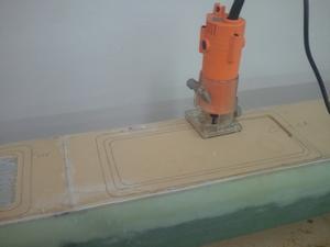
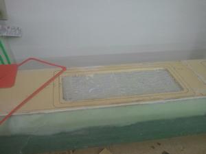
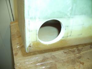
Here you can see I used a router to remove the foam. I tried two different methods. On one side, I cut away all the foam, but left the fiberglass intact. On the other side, I removed both the fiberglass and the foam. I wanted to see if it was easier to layup the outer fiberglass on top of the inner fiberglass, then trim the middle part out after it cured. The other method had a hole in the center, so the fiberglass needed to be trimmed before it cured.
Step 10 - Installing in the fuselage
Details of step will go here
